1 | Overview
2
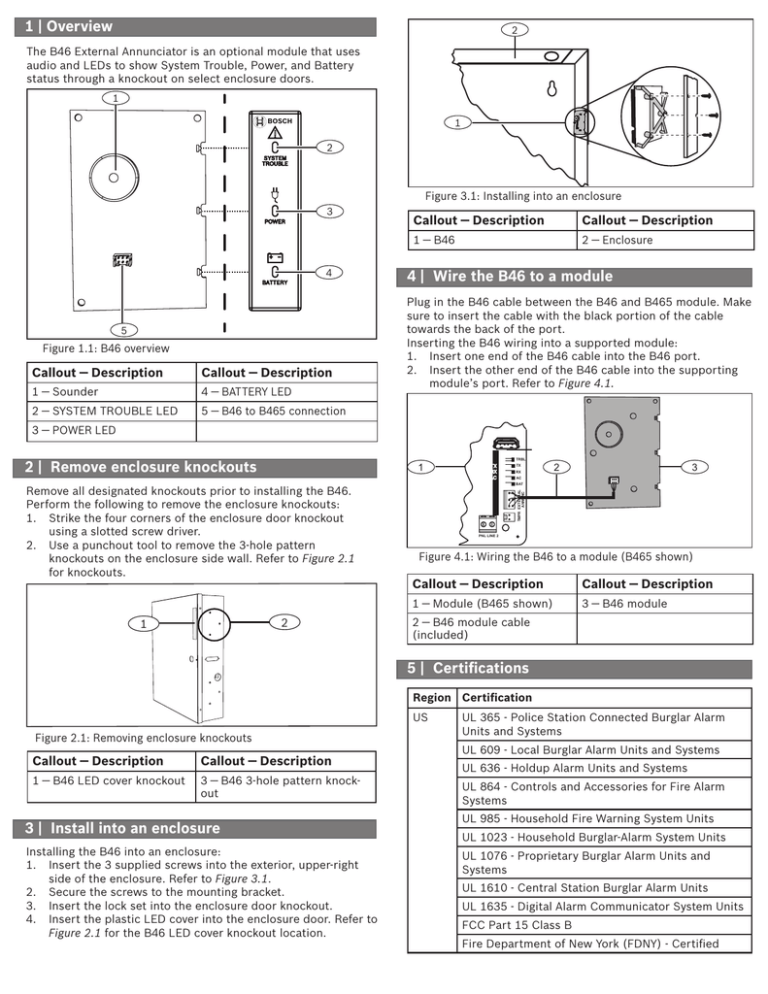
The B46 External Annunciator is an optional module that uses
audio and LEDs to show System Trouble, Power, and Battery
status through a knockout on select enclosure doors.
1
1
BOSCH
2
Figure 3.1: Installing into an enclosure
3
4
5
Figure 1.1: B46 overview
Callout ― Description
Callout ― Description
1 ― Sounder
4 ― BATTERY LED
2 ― SYSTEM TROUBLE LED
5 ― B46 to B465 connection
Callout ― Description
Callout ― Description
1 ― B46
2 ― Enclosure
4 | Wire the B46 to a module
Plug in the B46 cable between the B46 and B465 module. Make
sure to insert the cable with the black portion of the cable
towards the back of the port.
Inserting the B46 wiring into a supported module:
1. Insert one end of the B46 cable into the B46 port.
2. Insert the other end of the B46 cable into the supporting
module’s port. Refer to Figure 4.1.
3 ― POWER LED
USB
2 | Remove enclosure knockouts
1
2
1
TRBL
TX
RX
3
2
AC
BAT
TMPR EXTERNAL
ANNUNC
Remove all designated knockouts prior to installing the B46.
Perform the following to remove the enclosure knockouts:
1. Strike the four corners of the enclosure door knockout
using a slotted screw driver.
2. Use a punchout tool to remove the 3-hole pattern
knockouts on the enclosure side wall. Refer to Figure 2.1
for knockouts.
TX
TX
RX
AC
PNL LINE 2
Figure 4.1: Wiring the B46 to a module (B465 shown)
Callout ― Description
Callout ― Description
1 ― Module (B465 shown)
3 ― B46 module
2 ― B46 module cable
(included)
5 | Certifications
Region Certification
US
Figure 2.1: Removing enclosure knockouts
Callout ― Description
Callout ― Description
1 ― B46 LED cover knockout
3 ― B46 3-hole pattern knockout
3 | Install into an enclosure
Installing the B46 into an enclosure:
1. Insert the 3 supplied screws into the exterior, upper-right
side of the enclosure. Refer to Figure 3.1.
2. Secure the screws to the mounting bracket.
3. Insert the lock set into the enclosure door knockout.
4. Insert the plastic LED cover into the enclosure door. Refer to
Figure 2.1 for the B46 LED cover knockout location.
UL 365 - Police Station Connected Burglar Alarm
Units and Systems
UL 609 - Local Burglar Alarm Units and Systems
UL 636 - Holdup Alarm Units and Systems
UL 864 - Controls and Accessories for Fire Alarm
Systems
UL 985 - Household Fire Warning System Units
UL 1023 - Household Burglar-Alarm System Units
UL 1076 - Proprietary Burglar Alarm Units and
Systems
UL 1610 - Central Station Burglar Alarm Units
UL 1635 - Digital Alarm Communicator System Units
FCC Part 15 Class B
Fire Department of New York (FDNY) - Certified
6Region
| Certifications
Certification
CA
CAN/ULC S303 - Local Burglar Alarm Units and Systems
CAN/ULC S304 - Signal Receiving Centre and Premise Alarm Control Units
ULC S545 - Residential Fire Warning System Control Units
ULC-ORD C1023 - Household Burglar Alarm System Units
ULC-ORD C1076 - Proprietary Burglar Alarm Units and Systems
ICES-003 - Digital Apparatus
6 | Specifications
Dimensions
5.5 in x 4.1 in x 1.7 in (140 mm x 105 mm x 44 mm)
Voltage (operating)
12 VDC nominal
Current
Standby or Alarm: 23 mA
Compatible enclosure
B10/B10R Medium Control Panel Enclosure
D8103 Universal Enclosure (requires B12 mounting plate)
Relitive humidity
Up to 93% non-condensing
Temperature (operating)
0° to +49° C (+32° to 120° F)
1
Static may cause temporary loss of communication when using any one of the above enclosures.
1
Copyright
This document is the intellectual property of Bosch Security Systems, Inc. and is protected by copyright. All rights reserved.
Trademarks
All hardware and software product names used in this document are likely to be registered trademarks and must be treated accordingly.
Bosch Security Systems, Inc. product manufacturing dates
Use the serial number located on the product label and refer to the Bosch Security Systems, Inc. website at
http://www.boschsecurity.com/datecodes/.
External Annunciator
B46
Bosch Security Systems, Inc.
130 Perinton Parkway
Fairport, NY 14450
USA
Bosch Sicherheitssysteme GmbH
Robert-Bosch-Ring 5
85630 Grasbrunn
Germany
www.boschsecurity.com
© 2015 Bosch Security Systems, Inc.
en Installation Guide
F.01U.312.441 | 02 | 2015.05


