RELAY
CAT.
RM4
ALARM RELAY
Activates auxiliary devices from smoke,
CO and/or heat alarm signal.
120V AC, 60Hz Wire-in
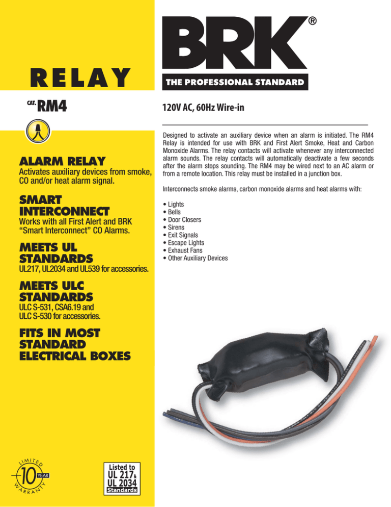
Designed to activate an auxiliary device when an alarm is initiated. The RM4
Relay is intended for use with BRK and First Alert Smoke, Heat and Carbon
Monoxide Alarms. The relay contacts will activate whenever any interconnected
alarm sounds. The relay contacts will automatically deactivate a few seconds
after the alarm stops sounding. The RM4 may be wired next to an AC alarm or
from a remote location. This relay must be installed in a junction box.
Interconnects smoke alarms, carbon monoxide alarms and heat alarms with:
SMART
INTERCONNECT
Works with all First Alert and BRK
“Smart Interconnect” CO Alarms.
MEETS UL
STANDARDS
UL217, UL2034 and UL539 for accessories.
MEETS ULC
STANDARDS
ULC S-531, CSA6.19 and
ULC S-530 for accessories.
FITS IN MOST
STANDARD
ELECTRICAL BOXES
• Lights
• Bells
• Door Closers
• Sirens
• Exit Signals
• Escape Lights
• Exhaust Fans
• Other Auxiliary Devices
CAT.
RM4
TECHNICAL SPECS
This accessory relay is designed to activate auxiliary devices such as bells, lights
and door closers. The RM4 Relay is intended for use with BRK and First Alert
Smoke, Heat, and Carbon Monoxide Alarms.
Alarm
AC
Power
Auxiliary Device
AC Power
BRK
Relay
Module
BRK
Alarm
Dimensions:
Weight:
Operating Voltage:
Operating Current:
Temperature Range:
Humidity Range:
3.5 L x 1.5 H
2.2 oz
120V AC 60Hz
.02 amps (standby/alarm)
40°F (4°C) to 100°F (38°C)
10% to 90% relative humidity (RH)
Interconnections:
Up to 18 units of First Alert or BRK Smoke, CO and
Heat Alarms. Maximum of 12 smoke alarms. See
user’s manual for details.
Listing:
Meets UL217, UL2034, UL539,ULC S-531,
CSA6.19 and ULCS-530 for accessories.
Auxiliary
Device
ARCHITECTURAL AND ENGINEERING SPEC
To install this relay to an alarm, connect the power wires as listed below. See diagram
for connections. Note: If wiring the relay remote from the alarm, use a maximum of
1000 feet [300 meters] of #18AWG or larger wire rated at least 300V.
ALARM
BLACK WIRE
WHITE WIRE
ORANGE WIRE
CONNECTION
(HOT)
(NEUTRAL)
(INTERCONNECT)
RELAY
BLACK WIRE
WHITE WIRE
ORANGE WIRE
Now connect the accessory to be activated by the relay to the relay’s switch contact
wires as listed below. (Use wiring appropriate to the auxiliary device being controlled.)
NOTE: Since voltage is present on all relay contact wires at some time during operation,
the installer must properly insulate any unused relay contact wire.
BROWN WIRE:
GRAY WIRE:
BLUE WIRE:
HOT CONTACT TO AUXILIARY DEVICE
NORMALLY CLOSED CONTACT
NORMALLY OPEN CONTACT
WHITE
BROWN
(COM.)
GRAY
(N.C.)
ORANGE
BLUE
(N.O.)
BLACK
NEUTRAL
WHITE
ORANGE BLACK
SHIPPING SPECS:
Individual Bag Dim. (Approx.)
Weight
Cube
UPC
6.25"L x 1.50"W x 5.00"H
0.16 lbs.
0.03 ft3
0 29054 00057 6
Master Carton Dimensions
Master Pack
Weight
Cube:
I2of5:
10.25"L x 4.75"W x 6.38"H
12
2.1 lbs.
0.19 ft3
100 29054 00057 3
Pallet Information
Cases per Layer
Number of Layers:
Cases per Pallet:
Units per Pallet:
Cube:
Weight:
35
6
210
2,520
54.7 ft3
695 lbs.
INTERCONNECT
UNSWITCHED 120V AC
60 Hz SOURCE
{
{
HOT
TO ADDITIONAL ALARMS
CONTACT RATINGS (MAXIMUM):
VOLTAGE
RESISTIVE
MOTOR
120V AC
15 AMP
1/3 H.P.
30V
DC 15 AMP
After installation, test the interaction of the auxiliary
device with the alarm by pressing the alarm test button.
©2009 BRK Brands, Inc. a Jarden Corporation
Company (NYSE: JAH)
brkelectronics.com
3901 Liberty Street Road
Aurora, IL 60504-8122
All rights reserved
First Alert is a registered trademark of the First Alert Trust
BRK is a registered trademark of BRK Brands, Inc.
CM2946


