EE301 Lecture handout
advertisement

EE301 – Lesson 34
Reading: 23.1-23.8
THREE PHASE SOURCES AND LOADS
Learning Objectives
(a)
(b)
(c)
(d)
(e)
Review the induced AC voltage output for a three phase AC generator as a function of time and as phasors.
Define a three-wire Y-Y three phase circuit and a four-wire Y-Y three phase circuit.
Define the symbols for line to neutral voltages, line to line voltages, line currents, and phase impedances
that will be used in three phase circuits.
Analyze Ohm’s law in a three-wire Y-Y three phase circuit and in a four-wire Y-Y three phase circuit using
a basic three phase generator that produces three balanced voltages which are connected to balanced loads.
Analyze Kirchhoff’s current law in a three-wire Y-Y three phase circuit and in a four-wire Y-Y three phase
circuit using a basic three phase generator that produces three balanced voltages with a Y connected
balanced purely resistive loads.
A three-phase source generates three separate ac voltage signals, all of the same peak value, but
differing from each other by a phase separation of 120. All commercial power in the U.S. is distributed
and delivered as a three phase voltage. (Which raises the obvious question: Why would we do such a
thing? -- We will defer that question until after we learn to analyze three-phase systems.)
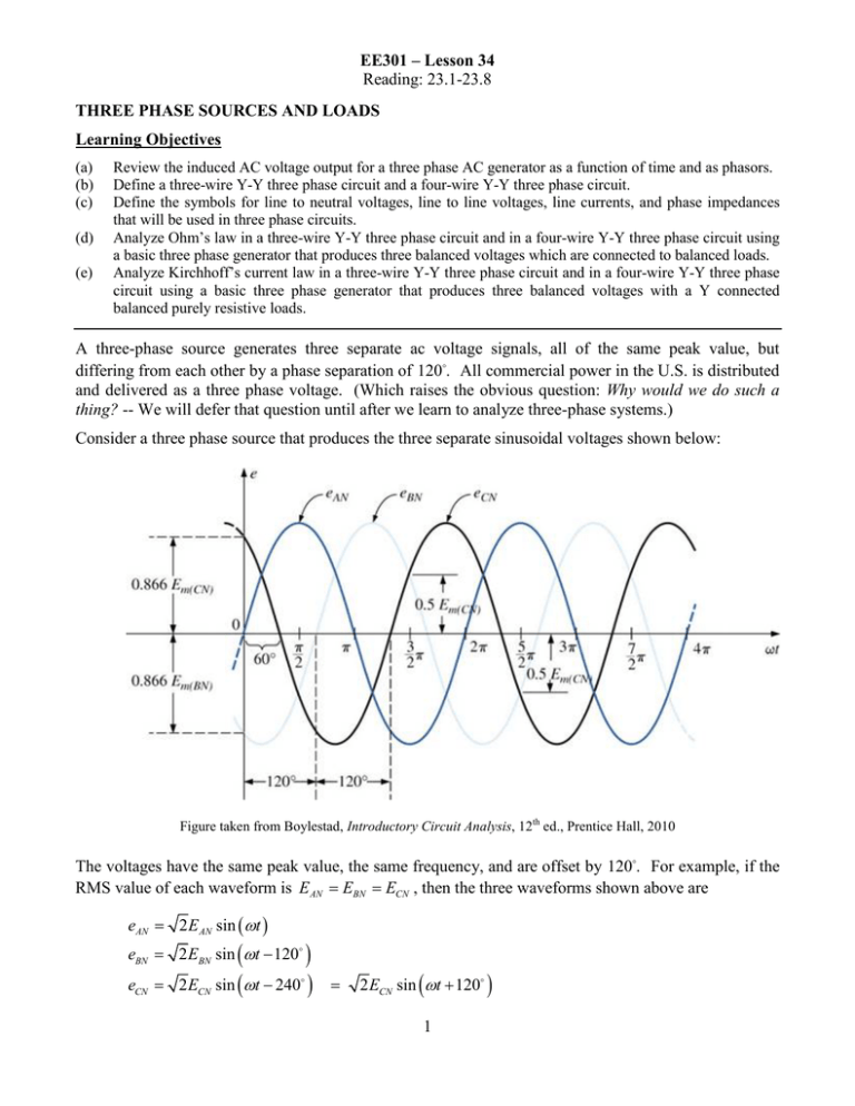
Consider a three phase source that produces the three separate sinusoidal voltages shown below:
Figure taken from Boylestad, Introductory Circuit Analysis, 12th ed., Prentice Hall, 2010
The voltages have the same peak value, the same frequency, and are offset by 120. For example, if the
RMS value of each waveform is E=
E=
ECN , then the three waveforms shown above are
AN
BN
eAN = 2 E AN sin (ωt )
=
eBN
=
eCN
2 EBN sin (ωt − 120 )
2 ECN sin=
(ωt − 240 )
2 ECN sin (ωt + 120 )
1
EE301 – Lesson 33
Reading: 23.1-23.8
Our three voltages can be represented as phasors:
E=
E AN ∠0
AN
E BN
= EBN ∠ − 120
E=
ECN ∠120
CN
What is the sum of our three sinusoids eAN + eBN + eCN at any moment of time?
eAN +=
eBN + eCN
2 E AN sin (ωt ) + 2 EBN sin (ωt − 120 ) + 2 ECN sin (ωt + 120 )
If E=
E=
E=
E this becomes
AN
BN
CN
eAN + eBN +
=
eCN
(
2 E sin (ωt ) + sin (ωt − 120 ) + sin (ωt + 120 )
)
Using trig identities, it is not hard to show that the sum on the right is always equal to zero. Thus,
eAN + eBN + eCN =
0
The Y-Connected Generator In the Y-connected generator, our three voltage sources above are
connected as shown below.
IA
E AN ∠0
ECN ∠ + 120
EBN ∠ − 120
IB
IC
Figure taken from Boylestad, Introductory Circuit Analysis, 12th ed., Prentice Hall, 2010
Note that the negative terminals of the three sources are connected together at the point labeled N, called
the neutral. Each of our three voltages in the arrangement above is termed a phase voltage. Our three
phase Y-connected generator is connected to a load via three lines. We have labeled the phasor currents
on each of these three lines as I A , I B and IC .
2
EE301 – Lesson 33
Reading: 23.1-23.8
Note the labeling of points A, B and C in the picture above. You might have the physical three-phase Yconnected generator shown below, where you have access only to the lines labeled A, B and C.
Specifically, it might be the case that you do not have access to the neutral point.
Since we only have access to the lines A, B and C, we are interested in the line voltages – the voltages
between the lines – which we denote E AB , E BC and E CA . So, in the picture below, let’s calculate the
line voltage E AB .
+
IA
E AN ∠0
E AB
ECN ∠ + 120
EBN ∠ − 120
IB
IC
Figure taken from Boylestad, Introductory Circuit Analysis, 12th ed., Prentice Hall, 2010
By KVL we have
= E AN ∠0 − EBN ∠ − 120 .
E AB
Since the RMS phase voltages are equal, let E=
E=
E , and our equation above becomes
AN
BN
E AB = E∠0 − E ∠ − 120
Shifting the right-hand side of the equation to rectangular coordinates, we have
3
EE301 – Lesson 33
Reading: 23.1-23.8
{
}
E AB =−
E E cos ( −120 ) + jE sin ( −120 )
Simplifying, we have
1
3
E AB = E − − E + jE
2
2
and simplifying further,
3
=
E AB E +
2
3
j
E
2
Converting this back to polar form yields the important result:
E
=
AB
3E ∠30
Using the same technique, we can solve for the other two line voltages:
E=
BC
3E ∠ − 90
=
E CA
3E ∠150
So, for a Y-connected generator, if we know the phase voltages we can immediately get the line
voltages, and vice versa:
Furthermore, there is no reason that the phase for E AN be fixed at zero. If the phase of E AN is θ , the
relationships between phase and line voltages are:
4
EE301 – Lesson 33
Reading: 23.1-23.8
Example Consider the three phase system shown on the left.
You are given one of the phase voltages:
EAN = 7620∠-18° V
Determine:
(a) EBN
(b) ECN
(c) The three line-to-line voltages
Solution:
Example Suppose ECN in a three-phase Y-connected generator is equal to 120∠150 . Determine EAN
and EBN.
Solution
Example Suppose EAN in a three-phase Y-connected generator is equal to 120∠ − 45 . Determine the
line voltage EAB.
Solution
Example Suppose the line voltage EAB in a three-phase Y-connected generator is equal to 480∠ 20 .
Determine the other two line voltages and all three phase voltages.
Solution
5
EE301 – Lesson 33
Reading: 23.1-23.8
The Y-Connected Generator With a Y-Connected Load
Suppose we connect a load to our Y-connected generator as shown below. A load in this configuration
is, for obvious reasons, called a Y-connected load. We would like to analyze this circuit; i.e., we would
like to determine the line currents and the various voltages.
In EE301 the load will always be balanced. That means, in the picture above, Z=
Z=
Z cn .
an
bn
Hmm… as far as analysis goes, this doesn’t look too pretty, does it?
Suppose we could connect a wire between the points labeled N and n above, resulting in this circuit:
Would this circuit be easier to analyze? Yes! Much easier! For example, I A =
Van
. But we can’t just
Z an
put wires into our circuit to make analysis easier. Or can we?
Let’s consider a concrete example. Suppose, in the figure above, with a wire connected between the
points labeled N and n, we have Z an= Z bn= Z cn= 12 Ω and EAN = 120∠0 . Then we can calculate I A ,
I B and IC as:
I A= 10∠0
I B= 10∠ − 120
IC= 10∠120
Then what is I N ?
I N = I A + I B + IC = 10∠0 + 10∠120 + 10∠ − 120
6
EE301 – Lesson 33
Reading: 23.1-23.8
But this is the same calculation we did at the top of page 2! Thus, I N = 0 !!!
So, what’s the point?
We can connect the wire from N to n without changing the circuit since no current flows in this wire.
But the addition of this wire makes circuit analysis easier!
Example In the circuit on the right, EAN = 277∠-30° V
(a) Determine all of the phase voltages and line voltages
(b) Determine the line currents.
Solution:
Y-Y system definitions
Line voltages are the voltages between the lines A, B and C (ECA, EAB, EBC, Vca, Vab, Vbc).
Phase voltages are the voltages across phases (EAN, EBN, ECN, VAN, VBN, VCN).
For the generator, EAN, EBN, ECN are the phase voltages.
For ∆ loads, phase voltage and line voltage are the same thing.
7
EE301 – Lesson 33
Reading: 23.1-23.8
Example (from text). Consider the balanced circuit shown below.
(a) Determine θ 2 and θ3 .
(b) Determine the line voltages.
(c) Determine the line currents.
(d) Repeat the problem if we remove the wire connecting N to n.
It is worth reiterating again:
For Y loads, line current and phase current are the same.
I a = Van / Z an
You should have gathered from the symmetry that for a Y-Y balanced circuit, if we know one current,
say I a , then we can immediately write down Ib and Ic . Specifically, if I a = I ∠θ then
Ib = I ∠θ − 120
Ic = I ∠θ + 120
8
EE301 – Lesson 33
Reading: 23.1-23.8
Example (from Robbins and Miller, Circuit Analysis, Theory and Practice, 4th ed, Delmar Cengage,
2007) . In the circuit shown below, V=
120∠0 .
an
(a) Determine the line currents.
(b) Determine E AN .
(c) Determine E AB .
9

