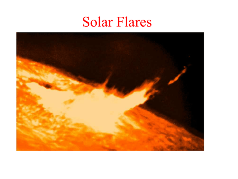
What is a solar flare?
advertisement

Solar Flares Solar Flare • A solar flare is a sudden brightening of solar atmosphere (photosphere, chromosphere and corona) • Flares release 1027 - 1032 ergs energy in tens of minutes. (Note: one H-bomb: 10 million TNT = 5.0 X 10²³ ergs) • A flare produces enhanced emission in all wavelengths across the EM spectrum, including radio, optical, UV, soft X-rays, hard X-rays, and γ-rays • Flare emissions are caused by - hot plasma emitting in: radio, visible, UV, soft X-ray -non-thermal energetic particles emitting in: radio, hard Xray, γ-rays Typical Flare Evolution in the Large-FlareProductive Phase Sigmoid along the inversion line Flare kernel brightening Post-flare loops Emerging bipoles into a coronal hole Emergence with “two bipoles” Flares at “dome intersection” Growing phase with occasional small flares Well-developed sigmoid structure Large-flare-productive phase (Morita and McIntosh 2005) Flare: Temporal Evolution • A flare may have three phases: • Preflare phase: sometimes • Impulsive phase: e.g., 10 min from 13:56 UT – 14:06 UT • Gradual phase: e.g., many hours after 14:06 UT • see Golub & Pasachoff, The Solar Corona, pag.288 Flare: Temporal Evolution • Pre-flare phase: flare trigger phase leading to the major energy release. It shows slow increase of soft X-ray flux • Impulsive phase: the flare main energy release phase. It is most evident in hard X-ray, γ-ray emission and radio microwave emission. The soft X-ray flux rises rapidly during this phase • Gradual phase: no further emission in hard X-ray, and the soft X-ray flux starts to decrease gradually. • Loop arcade (or arch) starts to appear in this phase Energy Source Eth ≈ 3nkTV = 1028 erg for pre-flare T =106K Emag ≈ (B2/2µ)V ≈ 1032 erg Only magnetic energy (Emag) is of the right order for the energy released in a large flare. Potential and non-potential magnetic field From Maxwell’s equations (neglecting displacement current): curl B = J where B = magnetic flux density and J is the current. When there is no current, curl B = 0, so B = grad φ i.e. B can be expressed in terms of a potential φ. There is zero energy available from a potential field. Flares derive their energy from non-potential magnetic fields (i.e. from currents). 1B11 MHD forces The Magnetic Force FM in a MHD plasma is FM =j x B. Using the Maxwell equations: B2 1 1 [ ( ∇ × B ) × B] = − ∇ + ( B • ∇ ) B = ..... FM = µ0 2µ 0 µ 0 And after a bit of lengthy algebra: B2 B2 RC FM = − ∇ ⊥ + 2 2 µ µ R 0 C 0 Rc is the local radius of curvature of the field line. It points towards the centre of curvature of the field line. Let us examine the two terms in the latter equation…. 1B11 MHD forces: two simple components B2 B2 RC FM = − ∇ ⊥ + 2 2 µ 0 µ 0 RC The magnetic force can be resolved into two conceptually simple components: • A force perpendicular to the B-field which has the form of a pressure (it is the gradient of a scalar quantity B2/2µ0), and • A force towards the instantaneous centre of curvature that depends on: i) radius of curvature and ii) field strength B. This is equivalent to a tension force acting along the field lines. Thus forcing the field lines together results in an opposing perpendicular pressure force, while trying to bend the field lines results in an opposing tension force. 1B11 MHD waves This magnetic pressure and magnetic tension represent two kinds of restoring force that arise in a plasma in the presence of a magnetic field. They are associated to wave modes: waves and perturbations that propagate in the plasma. Most important ones: 1) Alfven waves 2) Magnetosonic wave modes, in which both the magnetic field strength and the plasma pressure vary. 1B11 MHD waves The Alfven wave is a very important one. It is entirely due to the tension force associated with the magnetic field. • • It is essentially a magnetic wave, as there is no associated compression of the plasma as in the case of sonic (pressure) waves. It propagates preferentially along the field direction (and not across it) with speed: 2 VA = − B / µ 0ρ Magnetic Reconnection Magnetic Reconnection • Magnetic fields with opposite polarities are pushed together • At the boundary, B 0. • Called diffusion region, since plasma could cross B A simple example of magnetic reconnection. Two field lines of opposing polarity are forced together. When they meet they reconnect and snap back into a lower energy configuration. The upper loop is ejected into space, dragging plasma with it. 1B11 Magnetic reconnection If there is a strong B-field gradient and the fields on either side of the gradient are anti-parallel, then diffusion of the field at the gradient can led to a loss of total magnetic flux →this situation is called magnetic annihilation. Field lines are convected into the diffusion region and merge with field lines with opposite orientation (which originally where on the other side of the gradient) B field ⊕j E ⊕ ⊕ ⊕ ⊕ ⊕ Vin Diffusion 1B11 Magnetic reconnection Vout ~ V Alfven The resulting “reconnected lines” are sharply bent through the current sheet. Magnetic tension forces associated with these bent lines accelerate the plasma along the current sheet and away from the diffusion region on each side. ⊕j ⊕ Vin Diffusion B The simplest magnetic reconnection geometry. Anti-parallel field lines are separated by a thin current sheet (light grey) across which the field reverses. Due to the small scale lengths, the frozen-in flux approximation breaks down → magnetic flux diffuse from both sides. The field reconnects to form 2 hairpin like field lines, which rapidly contract away from the neutral “X”-point. Outflows jets of plasma are formed, also moving away from the “X”-point, on both sides. Magnetic merging - reconnection ∂B/∂t = ▼2 B / (σμ0) + curl (v × B) Rate of change of field in a flare volume = diffusive term + convective term. Get an order-of-magnitude estimate of quantities by approximating ∂/∂t = 1 / t, curl = 1 / L, ▼2 = 1 / L2: If there is no convective term, then: B/τD = B / (L2 σ μ0) or diffusion time, τD = L2 σ μ0. (4) Field lines form X-point and separatrix(curved surfaces in space that divide different bundles of flux.). small spatial lengths! the magnetic Reynolds number within the current sheet may be relatively small: → diffusion of the magnetic field through the plasma start to be important! The basic problem is that high-temperature coronal plasma, especially for flares, has an extremely large electrical conductivity σ (comparable to the conductivity of solid copper at room temperature). So the energy release timescale appears to be of the order of years rather than the observed seconds or minutes. diffusion time, τD = L2 σ μ0. The “classical” value of conductivity is σ = 10-3 Te3/2 S.I. units where Te = electron temperature. For the quiet corona, Te = 2 MK, so σ = 2.8 × 10⁶ S.I. units. (Solid copper has σ = 5 × 10⁷ S.I. units.) So the diffusive time scale τD for the pre-flare volume (take this to be L = 1,000 km = 106 m) is possibly as high as ~3.1012 s (billions of years). However, these simple estimates must be wrong for actual flares. It is likely that L ~ a few metres, not the observed flare dimensions which represent the “aftermath” of a flare, not the magnetic field diffusion region. Reconnection region (few m wide) X-type reconnection Plasma flow: reconnection “jet” Diffusion Region Field lines Limit:Stage gyroradius of electrons 1 Stage 2 Petschek reconnection takes place Sweet-Parker Petschek Inflow goes through diffusion region. Inflow goes through slow shock, bypassing diffusion region. vA vA Slow Shock δ vA L 1 = ~ 10 − 6 v A Rm ux0 = 2L ux0 ux0 = δ v A ~ 0.01v A y* 2y*Fast inflow Very slow inflow Too slow 2δ 2δ diffusion region Estimated inflow speed 0.07VA (Tsuneta 1996) 0.03VA (Yokoyama 2001) diffusion time, τ D = L2 σ μ0 . Petschek reconnection occurs if the anomalous resistivity sets in on the current sheet . Possible only for peculiar current sheet thickness current sheet thinning via the "fractal tearing instability" (Tanuma 2000; Shibata & Tanuma 2001; Tanuma et al. 2001a). the tearing mode gives rise to the formation of a magnetic island. Field-lines inside the separatrix have been broken and reconnected, and now possess quite different topology. Both the tearing-type and the Petschek-type reconnectionsdevelop from an initially antiparallel magnetic field. In the tearing-type field geometry the current-sheet plasma, accelerated at X-type neutral points through reconnection, cannot be ejected away from the system but is confined in the resulting magnetic islands. On the other hand, in the Petschek-type field geometry the plasma can freely be ejected away from the system, so that the antiparallel field is allowed to collapse into the X-type neutral point. Internal Shocks in the Reconnection Jet in Solar Flares Turbulence Dissipation Shocks region Shocks Turbulence S.Tanuma & K.Shibata (Kwasan Observatory, Kyoto University) Internal Shocks in Reconnection Jet • We suggest that the internal shocks could be created in the reconnection jet by the secondary tearing instability. • And the energetic electrons could be accelerated in the internal shocks. Tearing Instability 1. Initial current sheet linit A resistivity (η ) tears the current sheet. 0 2. LinearNonlinear init τ tearing ≈ (τ τ init init 1 / 2 A d ) linit ≈ init η v 0 A 3 1/ 2 λ tearing = 10 − 20linit 3. NonlinearPlasmoid-ejection The sheet becomes much thin by the secondary tearing instability so that annomalous resistivity is enhanced and the fast reconnection starts. (Furth et al. 1964) (Tanuma et al. 1999, 2001; Shibata & Tanuma 2001) 。 Simulation Results (Internal Shocks) *The current sheet thinning by the tearing instability *Slow (Sweet-Parker-like) reconnection and further thinning by secondary tearing instability *The onset of the anomalous resistivity Time variation of current sheet half-thickness Secondary tearing Tearing instability instability Fast reconnection *Fast (Petschek-like) reconnection and mutiple fast shocks Onset of the anomalous resistivity Creation of Plasmoids Many plasmoids are created (O-points) by the secondary tearing instability in the diffusion region and ejected z S.Tanuma & K.Shibata “..As the results, we find that many plasmoids are created by the secondary tearing instability. They are ejected, and the multiple fast shocks are created.“ (Fig: Karlicky 2004)


