Accessory Shelf
for the Mark V - 555953
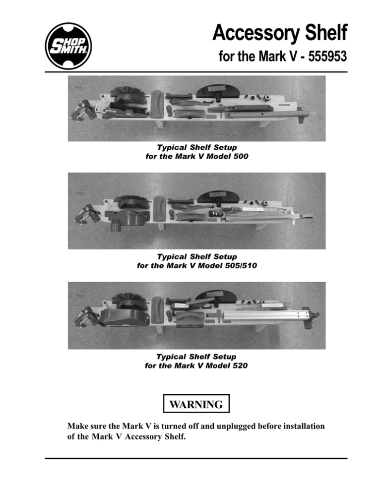
Typical Shelf Setup
for the Mark V Model 500
Typical Shelf Setup
for the Mark V Model 505/510
Typical Shelf Setup
for the Mark V Model 520
WARNING
Make sure the Mark V is turned off and unplugged before installation
of the Mark V Accessory Shelf.
Mark V Universal Accessory Shelf
555953
Tools Needed:
Parts List
7/16” Wrench
Pencil
3/16” Drill Bit
Electric Drill
Hammer or Mallet
INSTALLATION OF THE
MARK V ACCESSORY SHELF
Install the Wood Dowel Pins
in the Shelf
Ref
No.
Part
No.
Item
Description
—
1
2
3
4
5
6
555953
522248
522256
120392
517003
517001
522249
Mark V Accessory Shelf
. Shelf ............................................ 1
. Hardware Bag (incl. 3-6) .......... 1
. . Flat Washer .............................. 2
. . Lag Bolt ..................................... 2
. . Dowel Pin, 1/4” diameter ...... 1
. . Dowel Pin, 1/2” diameter ...... 1
Qty
Attach the Shelf to the Left Leg
1. Use a hammer or mallet to gently tap in the
wood pin (5) into the 1/4” diameter hole,
located near the shelf’s right front edge.
See Fig. 1.
2. Use a hammer or mallet to gently tap in the
wood pin (6) into the 1/2” diameter hole,
located near the shelf’s left leg cut-out. See
Fig. 2 for hole location.
5. As shown in Fig. 2, lift the shelf’s left
“notch” so it is centered in the top hole of
the left front leg. Working from inside of
the Mark V’s left leg, use a pencil to mark
the drill hole.
Inside of Mark V’s
left leg
Right Leg of Mark V,
on the switch side
Hole in Shelf’s
right leg notch.
1/2” Dowel
Pin Hole
Fig. 2
1/4” Dowel
Pin Hole
6. Rest the shelf on the floor. Use a 3/16”
drill bit to drill a ¾” deep hole a the pencil
mark.
Fig. 1
Attach the Shelf to the Right Leg
3. Place a flat washer (3) on a lag bolt (4).
Working on the switch/speed dial side of
the Mark V, insert the lag bolt through the
top hole of the right leg, from the inside, as
shown in Fig. 1.
7. Place a flat washer (3) on a lag bolt (4). Use
the 7/16” wrench to attach the shelf with
the lag bolt. Tighten the lag bolts on both
the left and right sides, see Fig. 3.
4. Thread the lag bolt in the hole located in
the shelf’s right leg notch, see Fig. 1. Use a
7/16” wrench to engage the lag bolt
threads into the shelf about halfway. Do
not tighten yet.
NOTE
6530 Poe Avenue
Dayton, Ohio 45414
If you have any questions, please call our Customer Service
Department TOLL-FREE at 1-800-762-7555, send us an e-mail at
techsupport@shopsmith.com, or visit our website at
www.shopsmith.com.
Fig. 3
845549
Rev A
03/04
©2004 Shopsmith, Inc.
All Rights Reserved
Printed In U.S.A.


