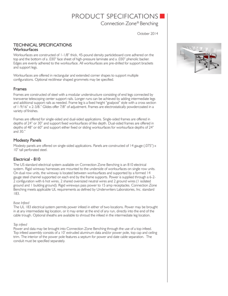
PRODUCT SPECIFICATIONS ■ Connection Zone® Benching October 2014 TECHNICAL SPECIFICATIONS Worksurfaces Worksurfaces are constructed of 1-1/8” thick, 45-pound density particleboard core adhered on the top and the bottom of a .030” face sheet of high-pressure laminate and a .030” phenolic backer. Edges are evenly adhered to the worksurface. All worksurfaces are pre-drilled for support brackets and support legs. Worksurfaces are offered in rectangular and extended corner shapes to support multiple configurations. Optional rectilinear shaped grommets may be specified. Frames Frames are constructed of steel with a modular understructure consisting of end legs connected by transverse telescoping center support rails. Longer runs can be achieved by adding intermediate legs and additional support rails as needed. Frame leg is a fixed height “goalpost” style with a cross section of 1-9/16” x 2-3/8.” Glides offer 7/8” of adjustment. Frames are electrostatically powdercoated in a variety of finishes. Frames are offered for single-sided and dual-sided applications. Single-sided frames are offered in depths of 24” or 30” and support fixed worksurfaces of like depth. Dual-sided frames are offered in depths of 48” or 60” and support either fixed or sliding worksurfaces for worksurface depths of 24” and 30.” Modesty Panels Modesty panels are offered on single-sided applications. Panels are constructed of 14 gauge (.075”) x 10” tall perforated steel. Electrical - 810 The US standard electrical system available on Connection Zone Benching is an 810 electrical system. Rigid wireway harnesses are mounted to the underside of worksurfaces on single row units. On dual row units, the wireway is located between worksurfaces and supported by a formed 14 gauge steel channel supported on each end by the frame supports. Power is supplied through a 6-22 configuration with 6 hot wires, 2 shared oversized neutral wires and 2 ground wires (1 isolated ground and 1 building ground). Rigid wireways pass power to 15 amp receptacles. Connection Zone Benching meets applicable UL requirements as defined by Underwriters Laboratories, Inc. standard 183. Base Infeed The UL 183 electrical system permits power infeed in either of two locations. Power may be brought in at any intermediate leg location, or it may enter at the end of any run, directly into the end of the cable trough. Optional sheaths are available to shroud the infeed in the intermediate leg location. Top infeed Power and data may be brought into Connection Zone Benching through the use of a top infeed. Top infeed assembly consists of a 10’ extruded aluminum data and/or power pole, top cap and ceiling trim. The interior of the power pole features a septum for power and date cable separation. The conduit must be specified separately. TECHNICAL SPECIFICATIONS (CONTINUED) Electrical - Hardwire Receptacle enclosures are constructed of 18 gauge galvanized metal in accordance with the National Electrical Code. Lengths are determined by table side height; height equals 2-1/2”, width equals 2-1/2”. Openings are for décor style receptacles and are located on one side for single worksurface units and on both sides for dual worksurface units. Floor infeeds are ¾” diameter liquid tight enclosed conduit. Top feeds are provided by field electrician and are run down an aluminum pole. Hardwire electrical components are intended for use in installations where hardwiring is required by local code (Chicago and New York City are examples). Table-to-Table Jumpers 18” jumpers feature flexible metal conduit. Receptacles 15-amp receptacles for the modular electrical system feature injection molded components which snap fit into the rigid wireways. Cable Management Dual-sided applications: Cable management trough is secured with a variable support bracket onto the understructure of the beam rails. The trough is evenly shared between the worksurfaces and is accessible from the top when specified with sliding worksurfaces. The trough is accessible from the underside of the structure when specified with fixed worksurfaces. Privacy and Divider Screens Privacy screens and divider screens are constructed with an aluminum frame that provides superior strength and can be powdercoated in frame matching colors or accent colors. The standard top rail provides a single slot that allows users to mount a paper management tool or an optional tool rail version containing (3) slots that allows mounting of additional accessories. Core material options include acrylic, markerboard and tackable upholstered fabric. Height options include 13” and 19” in all cores and an additional 31” tall tackable fabric version in limited widths. Single screens matching the lengths of the worksurfaces are available up to 78”. 60", 72" and 84” lengths are offered with center intersection to equally divide worksurfaces. 90” and 96” units are available in (2) or (3) equal segments. Privacy Screens are located flush with the bottom of the worksurfaces and run parallel with the support beam. On single row units, mounting brackets are attached directly to the bottom of the worksurfaces. On dual row units, mounting brackets are attached to the support frames. Divider screens rest on top of the surface and run perpendicular to privacy screens. Divider screens attach to the privacy screens on one end and are supported by worksurface attachment brackets on the other end. 1330 Bellevue Street • P.O. Box 8100 • Green Bay, WI 54308-8100 • 1-800-424-2432 • www.ki.com © 2014 Krueger International, Inc. All Rights Reserved • Code KI-62595R2/KI/PDF/1014
