Advanced Circuit Materials Division
100 S. Roosevelt Avenue
Chandler, AZ 85226
Tel: 480-961-1382, Fax: 480-961-4533
www.rogerscorp.com
Advanced Circuit Materials
Data Sheet
RT/duroid 6002 High Frequency Laminates
®
Features:
•
Low loss for excellent high frequency
performance.
•
•
Tight εr and thickness control.
•
Extremely low thermal coefficient of
dielectric constant.
•
In-plane expansion coefficient matched to
copper.
•
•
Low Z-axis expansion
Excellent electrical and mechanical
properties.
Low outgassing; Ideal for space applications.
Some Typical Applications:
•
•
•
•
•
•
Phase Array Antennas
•
Beam Forming Networks
Ground Based and Airborne Radar Systems
Global Positioning System Antennas
Power Backplanes
1.6002
RT/duroid® 6002 microwave material is the first low loss and
low dielectric constant laminate to offer superior electrical
and mechanical properties essential in designing complex
microwave structures which are mechanically reliable and
electrically stable.
The thermal coefficient of dielectric constant is extremely
low from -55oC to+150oC (-67°F to 302°F) which provides
the designers of filters, oscillators and delay lines the electrical stability needed in today’s demanding applications.
A low Z axis coefficient of thermal expansion (CTE) ensures
excellent reliability of plated through-holes. RT/duroid
6002 materials have been successfully temperature cycled
(-55oC to 125oC [-67°F to 257°F]) for over 5000 cycles without a single via failure.
Excellent dimensional stability (0.2 to 0.5 mils/inch) is
achieved by matching the X and Y coefficient of expansion to copper. This often eliminates double etching to
achieve tight positional tolerances.
High Reliability Complex Multilayer Circuits
Commercial Airline Collision Avoidance
Systems
The low tensile modulus (X,Y) greatly reduces the stress
applied to solder joints and allows the expansion of the
laminate to be constrained by a minimum amount of low
CTE metal, (6 ppm/oC) further increasing surface mount
reliability.
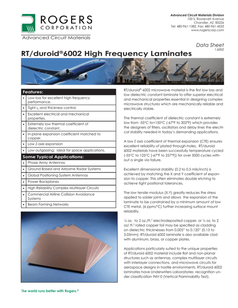
¼ oz. to 2 oz./ft.2 electrodeposited copper, or ½ oz. to 2
oz/ ft.2 rolled copper foil may be specified as cladding
on dielectric thicknesses from 0.005” to 0.120” (0.13 to
3.05mm). RT/duroid 6002 laminate is also available clad
with aluminum, brass, or copper plates.
Applications particularly suited to the unique properties
of RT/duroid 6002 material include flat and non-planar
structures such as antennas, complex multilayer circuits
with interlayer connections, and microwave circuits for
aerospace designs in hostile environments. RT/duroid 6002
laminates have Underwriters Laboratories recognition under classification 94V-0 (Vertical Flammability Test).
The world runs better with Rogers.®
Typical Values
RT/duroid 6002 Laminates
Property
Typical Value
Direction
Units [1]
Conditions
Test Method
Dielectric Constant, εr
Process
2.94 ± 0.04
Z
-
10GHz/23°C
IPC-TM-650, 2.5.5.5
Dielectric Constant, εr
Design
2.94
8GHz-40GHz
Differential Phase Length
Method
Dissipation Factor,
TAN δ
0.0012
Z
-
10 GHz/23°C
IPC-TM-650, 2.5.5.5
Thermal Coefficient
of εr
+12
Z
ppm/°C
10 GHz
0-100°C
IPC-TM-650, 2.5.5.5
Volume Resistivity
106
Z
Mohm cm
A
ASTM D257
Surface Resistivity
107
Z
Mohm
A
ASTM D257
828 (120)
X,Y
MPa (kpsi)
Ultimate Stress
6.9 (1.0)
X,Y
MPa (kpsi)
23°C
ASTM D638
Ultimate Strain
7.3
X,Y
%
2482 (360)
Z
MPa (kpsi)
Moisture Absorption
0.02
-
%
D48/50
IPC-TM-650, 2.6.2.1
ASTM D570
Thermal Conductivity
0.60
-
W/m/K
80°C
ASTM C518
Coefficient of
Thermal Expansion
16
16
24
X
Y
Z
ppm/°C
(10K/min)
TMA
ASTM D3386
IPC-TM-650 2.4.41
Td
500
°C TGA
ASTM D3850
Density
2.1
gm/cm3
ASTM D792
Tensile Modulus
Compressive
Modulus
Specific Heat
0.93 (0.22)
Copper Peel
8.9 (1.6)
Flammability
V-O
Lead-Free Process
Compatible
YES
-
J/g/K (BTU/lb/°F)
ASTM D638
-
lbs/in (N/mm)
Calculated
IPC-TM-650 2.4.8
UL94
Typical value are a representation of an average value of the population of the property. For specification values contact Rogers Corporation.
[1] S1 units given first, with other frequenlty used units in parentheses
[2] References: internal TRs 3824, 5016, 5017, 5035. Test were at 23°C unless otherwise noted.
STANDARD THICKNESS:
STANDARD PANEL SIZE:
STANDARD COPPER CLADDING:
0.005” (0.127mm)
0.010” (0.254mm)
0.020” (0.508mm)
0.030” (0.762mm)
0.060” (1.524mm)
0.120” (3.048mm)
18” X 12” (457 X 305mm)
18” X 24” (457 X 610mm)
¼ oz. (8.5 μm) electrodeposited copper foil.
½ oz. (17μm), 1 oz. (35μm), 2 oz. (70μm) electrodeposited and rolled copper foil.
Unclad material 0.020” or greater is available.
Thick metal claddings are available.
Additional claddings and panel sizes are available.
Contact customer service for more information.
The information in this data sheet is intended to assist you in designing with Rogers’ circuit material laminates. It is not intended to and
does not create any warranties express or implied, including any warranty of merchantability or fitness for a particular purpose or that
the results shown on this data sheet will be achieved by a user for a particular purpose. The user should determine the suitability of
Rogers’ circuit material laminates for each application.
These commodities, technology and software are exported from the United States in accordance with the Export Administration regulations. Diversion contrary to U.S. law prohibited.
RT/duroid, The world runs better with Rogers. and the Rogers’ logo are licensed trademarks of Rogers Corporation
© 1987, 1988, 1992, 1999, 2005, 2010 Rogers Corporation, Printed in U.S.A., All rights reserved
Revised04/13/2011 -0411-.5-CC Publication# 92-102


