LCM: Lightweight Communications and
advertisement
LCM: Lightweight Communications and Marshalling
Albert S. Huang, Edwin Olson, David C. Moore
Abstract— We describe the Lightweight Communications and
Marshalling (LCM) library for message passing and data
marshalling. The primary goal of LCM is to simplify the
development of low-latency message passing systems, especially
for real-time robotics research applications.
Messages can be transmitted between different processes
using LCM’s publish/subscribe message-passing system. A
platform- and language-independent type specification language
separates message description from implementation. Message
specifications are automatically compiled into language-specific
bindings, eliminating the need for users to implement marshalling code while guaranteeing run-time type safety.
LCM is notable in providing a real-time deep traffic inspection tool that can decode and display message traffic
with minimal user effort and no impact on overall system
performance. This and other features emphasize LCM’s focus
on simplifying both the development and debugging of message
passing systems. In this paper, we explain the design of LCM,
evaluate its performance, and describe its application to a
number of autonomous land, underwater, and aerial robots.
I. I NTRODUCTION
A fundamental software design principle is that of modularity, which promotes maintainability, code re-use, and fault
isolation [1]. A large robotic system, for example, can be
decomposed into specific tasks such as data acquisition, state
estimation, task planning, etc. To accomplish their tasks,
modules must exchange information with other modules.
With modern operating systems, it is convenient to map
individual modules onto software processes that can be on
the same or physically separate computational devices. This
then transforms the task of information exchange into the
well studied problem of interprocess communication.
In this paper, we describe a message passing system
for interprocess communication that is specifically targeted
for the development of real-time systems. Our approach
is motivated by lessons from modern software practices,
and places great emphasis on simplicity and usability from
the perspective of a system designer. We call our system
Lightweight Communications and Marshalling (LCM) to
signify its functionality and its simplicity in both usage and
implementation.
The single most notable attribute of mapping modules
onto separate processes is that every module receives a
separate memory address space. The introduction of this
barrier provides a number of benefits; modules can be run on
Huang is at the Computer Science and Artificial Intelligence Laboratory at MIT, Cambridge, MA, USA. Olson is in the Computer
Science and Engineering department at the University of Michigan,
Ann Arbor, MI, USA. Moore is a software engineer at Dreamworks
SKG, Inc.
the same or different host devices, started and stopped independently, written in different programming languages and
for different operating systems, and catastrophic failure of
one module (e.g. a segmentation fault) does not necessarily
impact another.
With this independence also comes isolation – sharing
information between modules is no longer a trivial task.
Module designers must carefully consider what information
to share across modules, how to marshal (encode) that information into a message, how to communicate a marshalled
message from one module to another, and how to un-marshal
(decode) the message once received.
Although a message passing system introduces complexities that must be carefully managed, it also provides opportunities for analysis and introspection that may be invaluable
to a developer. In particular, messages may be captured and
analyzed by modules specifically designed to aid system
development. Such modules might log messages to disk,
provide statistics on bandwidth, message rate, etc. If the
messages are marshalled according to a formal type system,
then a traffic inspection module could automatically decode
messages in much the same way a program debugger can
automatically decode stack variables of a running application.
LCM provide tools for marshalling, communication, and
analysis that are both simple to use and highly efficient.
Its overarching design philosophy is to make it easy to
accomplish the most common message passing tasks, and
possible to accomplish most others. LCM also detects many
run-time errors, such as invalidly formatted data and type
mismatches.
II. R ELATED W ORK
Interprocess communication is an extensively studied topic
with broad applicability. We direct our attention specifically
towards its use in developing robotic systems, where the
idea of dividing large systems into modules has become
commonplace [2], [3].
There are several recurring themes in existing systems.
Publish/subscribe models are the most commonly used [4],
[2], [5], with TCP being the most common transport. Most
of these systems employ a centralized hub, whether it is
used for message routing or merely for “match making”.
Virtually all of these systems provide a reliable and ordered
transport system, though some of the systems provide a
UDP transport as a non-standard option. A separate technical
report describes a number of commonly used systems in
greater detail [6].
Existing systems are widely varied in terms of provided
support for data marshalling. Some systems do not provide automatic marshalling tools, instead allowing free-form
human-readable messages [4], or specifying a set of standardized messages and binary formats [7]. Several systems
use an XDR-based marshalling system [8], [9], [2], though
some implementations provide only partially automatic code
generation. Language and platform support is typically limited, and with some systems [2], the users must manually
keep a formatting string in sync with the message layout.
Our system, Lightweight Communications and Marshalling (LCM), provides a “push”-based publish/subscribe
model. It uses UDP multicast as a low-latency but unreliable
transport, thus avoiding the need for a centralized hub. LCM
provides tools for generating marshalling code based on a
formal type declaration language; this code can be generated
for a large number of platforms and operating systems and
provides run-time type safety.
Several of the other systems provide an operating “environment”, consisting of pre-defined data types, ready-touse modules, event loops, message-passing systems, visualization and simulation tools, package management, and
more [2], [3], [4]. LCM is different in that it is intended
to be an “a la carte” message passing system, capable of
being integrated into a wide variety of systems.
Finally, the way in which LCM is perhaps most distinctive from other systems is in its emphasis on debugging
and analysis. For example, while all systems provide some
mechanism for delivering a message from one module to
another, few provide a way to easily debug and inspect the
actual messages transmitted. Those that do typically do so
at the expense of efficiency and performance. LCM provides
a tool for deep inspection of all messages passed on the
network, requiring minimal developer effort and incurring no
performance penalty. This is made possible by design, and
allows a system developer to quickly and efficiently identify
many bugs and potential sources of failure that are otherwise
difficult to detect.
III. A PPROACH
We divide our description of LCM into several sections:
type specification, marshalling, communications, and tools.
Type specification refers to the method and syntax for defining compound data types, the sole means of data interchange
between processes using LCM. Marshalling is the process of
encoding and decoding such a message into binary data for
the communications system which is responsible for actually
transmitting it.
A. Type Specification
Processes communicating with LCM agree in advance
on the compound data types used to represent information.
LCM does not support defining Remote Procedure Calls
(RPC), and instead requires applications to communicate by
exchanging individual messages. This restriction makes the
LCM messaging protocol stateless, simplifying other aspects
of the system (particularly logging and playback). To aid this
process, LCM defines a formal type specification language
for describing messages.
The binary representation of a message is implicitly defined by its type definition. These definitions are independent
of platform and programming language, and a code generation tool is used to automatically generate language-specific
bindings that provide representations of the message in a
form native to the programming language. Fig. 1 shows an
example of two LCM message type definitions, and Fig. 2
demonstrates use of the C language bindings.
struct waypoint_t {
string id ;
float position [ 2 ] ;
}
struct path_t {
int64_t timestamp ;
int32_t num_waypoints ;
waypoint_t waypoints [ num_waypoints ] ;
}
Fig. 1. Two example LCM types. The first contains two fields, one of
which is a fixed-length array. The second is a compound type, and contains
a variable length array in addition to two primitive data types.
#include <lcm / lcm . h>
#include "waypoint_t.h"
#include "path_t.h"
int main ( int argc , char
waypoint_t wp [ 2 ] ;
wp [ 0 ] . id
=
wp [ 0 ] . position [ 0 ] =
wp [ 0 ] . position [ 1 ] =
wp [ 1 ] . id
=
wp [ 1 ] . position [ 0 ] =
wp [ 1 ] . position [ 1 ] =
∗∗argv ) {
"waypoint 0" ;
0.0;
0.0;
"waypoint 1" ;
100;
100;
path_t path ;
path . timestamp = 0 ;
path . num_waypoints = 2 ;
path . waypoints = wp ;
lcm_t ∗lcm = lcm_create ( NULL ) ;
path_t_publish ( lcm , "PATH_CHANNEL" , &path ) ;
}
Fig. 2. A complete C program showing how to declare and transmit
a message using the automatically generated C-language bindings for the
types defined in Fig. 1. LCM also supports message type bindings for
Python, Java, and MATLAB.
The types in Fig. 1 show the basic structure of LCM types.
The LCM documentation and a separate technical report [6]
contain a comprehensive description of the type specification
language and additional features such as namespaces and
constants.
The LCM type specification was strongly influenced by
the External Data Representation (XDR) [8], which is used
by Sun Remote Procedure Calls (Sun/RPC) and the Network
File System (NFS) [10]. Some XDR features, such as pointer
chasing and unions, are not supported by LCM due to the
fact that they are rarely used, have portability issues, or invite
user error.
LCM also provides features and other usability improvements over XDR. For example, LCM provides a simple
method for declaring the length of a variable-length array;
in contrast, the XDR specification does not specify how the
length of arrays should be specified, which has led to a
variety of incompatible approaches. A second example is
LCM’s support for namespaces, which make it easier to avoid
naming conflicts when sharing code with others.
B. Marshalling
In order for two modules to successfully communicate,
they must agree exactly on how to interpret the binary
contents of a message. If the interpretations are different,
the resulting system behavior is typically undefined, and
usually unwanted. In some cases, these problems can be
obvious and catastrophic: a disagreement in the signedness of
a motor control message, for example, could cause the robot
to suddenly jump to maximum reverse power when the value
transitions from 0x7f to 0x80. In other cases, problems can
be more subtle and difficult to diagnose.
Additionally, as a system evolves, the messages may
change as new information is required and obsolete information is removed. Thus, message interpretation must be
synchronized across modules as messages are updated.
Fingerprint: Type checking in LCM is accomplished by
prepending each LCM message with a 64-bit fingerprint
derived from the type definition. The fingerprint is a hash
of the member variable names and types. If the LCM type
contains member variables that are themselves LCM types,
the hash recursively considers those member variables. The
details of computing a hash function are straight-forward
and thoroughly documented within the LCM source code
distribution, so we omit a detailed description here.
In the common case, an LCM client knows what type
of message is expected on a particular messaging channel.
When a message is received by an LCM client, it first reads
the fingerprint of the message. If the fingerprint does not
match the LCM client’s expected fingerprint, a type error is
reported.
LCM clients can also build a fingerprint database, allowing
them to identify the type of message when it is received. This
is the technique used by our tool lcm-spy, which allows realtime deep inspection of LCM traffic.
C. Communications
The communications aspect of LCM can be summarized
as a publish-subscribe messaging system that uses UDP
multicast as its underlying transport layer. Under the publishsubscribe model, each message is transmitted on a named
channel, and modules subscribe to the channels required
to complete their designated tasks. It is typically the case
(though not enforced by LCM) that all the messages on a
particular channel are of a single pre-specified type.
1) UDP Multicast: In typical publish-subscribe systems,
a mediator process is used to maintain a central registry of
all publishers, channels, and subscribers. Messages are then
either routed through the mediator directly, or the mediator
is used to broker point-to-point connections between a publisher and each of its subscribers. In both cases, the number
of times a message is actually transmitted scales linearly with
Fig. 3. LCM-spy screenshot. lcm-spy is a traffic inspection tool that is
able to automatically decode and display LCM messages in real-time. It
requires only that the automatically generated Java code for the LCM types
be accessible in the class path; no additional developer effort is required.
the number of subscribers. When a message has multiple
subscribers, this overhead can become substantial.
The approach taken by LCM, in contrast, is simply to
broadcast all messages to all clients. A client discards those
messages to which it is not subscribed. Communication
networks such as Ethernet and the 802.11 wireless standards
make this an efficient operation, where transmitted packets
are received by all devices regardless of destination.
LCM bases its communications directly on UDP multicast,
which provides a standardized way to leverage this feature.
Consequently, it does not require a centralized hub for either
relaying messages or for “match making”. A maximum LCM
message size of 4 GB is achieved via a simple fragmentation
and reassembly protocol. The multicast time-to-live parameter is used to control the scope of a network, and is most
commonly set to 0 (all software modules hosted on the same
computational device) or 1 (modules spread across devices
on the same physical network).
2) Delivery Semantics: LCM provides a best-effort packet
delivery mechanism and gives strong preference to the expedient delivery of recent messages, with the notion that the additional latency and complexity introduced by retransmission
of lost packets does not justify delaying newly transmitted
messages.
In general, a system that has significant real-time constraints, such as a robot, may often prefer that a lost packet
(e.g., a wheel encoder reading) simply be dropped rather than
delay future messages. LCM reflects this in its default mode
of operation; higher level semantics may still be implemented
on top of the LCM message passing service.
D. Tools
LCM provides several tools useful for logging, replaying,
and inspecting traffic (Fig. 3). Together, they allow a developer to rapidly and efficiently analyze the behavior and
performance of an LCM system.
The logging tools are similar to those found in many
messaging systems, and allow LCM traffic to be recorded to a
file for future playback or analysis. We note that the logging
and playback programs are not attributed special status in
Echo Test Achieved Bandwidth, 1 client
Echo Test Achieved Bandwidth, 2 clients
35
60
LCM C
LCM Java
IPC (central −c)
IPC
ROS (TCP, q=100)
ROS (TCP, q=∞)
0.6%(•)
10.2%(°)
3.7%(°)
20
0.3%(•)
15
0.3%(°)
10
6.9%(*)
5
0
32.1%(*)
27.8%(*)
65.7%(*)
70
8.0%(•)
73.8%(*)
40
0.7%(•)
30
19.8%(°)
46.5%(°)
1.0%(°)
0.3%(•)
0.2%(°)
20
23.1%(*) 42.2%(*)
4.1%(*)
10
61.4%(*)
73.2%(*)
Receive Rate (MB/s)
25
80
50
Receive Rate (MB/s)
Receive Rate (MB/s)
30
Echo Test Achieved Bandwidth, 4 clients
90
8.0%(•)
2.0%(•)
10.8%(•)
60
50
5.0%(°)
40
20.7%(°)
10.2%(•)
43.2%(°)
45.6%(•)
0.6%(°)
30
33.7%(*)
20
1.0%(*)
70.7%(*)
79.8%(*)
55.0%(*)
10
0
5
10
15
20
25
Attempted Transmit Rate (MB/s)
0
30
0
5
10
15
20
25
Attempted Transmit Rate (MB/s)
0
30
0
5
10
15
20
Attempted Transmit Rate (MB/s)
25
Fig. 4. Bandwidth results from an echo test with 1, 2, and 4 clients, where each client echoes messages transmitted by a single sender. The bandwidth
of successful echoes as detected by the original sender are shown. Message loss rates (messages with no received echo) are shown in parentheses when
nonzero.
Packet Round Trip Time, 1 client
6
10
Packet Round Trip Time, 2 clients
6
Packet Round Trip Time, 4 clients
6
10
LCM C
10
IPC (central −c)
IPC
ROS (TCP, q=100)
ROS (TCP, q= ∞)
2
10
0
10
−2
10
Average round−trip time (ms)
Average round−trip time (ms)
Average round−trip time (ms)
LCM Java
4
10
4
10
2
10
0
10
−2
0
5
10
15
20
25
Attempted transmit bandwidth (MB/s)
30
10
4
10
2
10
0
10
−2
0
5
10
15
20
25
Attempted transmit bandwidth (MB/s)
30
10
0
5
10
15
20
Attempted transmit bandwidth (MB/s)
25
Fig. 5. Mean message round-trip times for the echo test in Fig. 4 with 1, 2, and 4 clients. Average round-trip times are shown on a log scale; these times
do not reflect lost packets (which essentially have an infinite round-trip time). Both LCM implementations offer low latency. While IPC (using central -c)
also appears to provide low latency, it is critical to notice that IPC’s achieved bandwidth fell short of the target bandwidth (see Fig. 4).
LCM; the logger simply subscribes to all channels, and the
replay tool publishes messages from a data file.
Spy: If a database of every LCM type used on a system
is assembled, then an arbitrary fingerprint serves as a type
identifier with very high probability.1 The lcm-spy tool is
designed to leverage this attribute, and is able to analyze,
decode, and display live traffic automatically with virtually
no programmer effort. Fig. 3 shows a screenshot of lcm-spy
inspecting traffic.
lcm-spy is implemented in Java, and requires only that the
classpath contain the automatically generated Java versions
of each type. Using the reflection features of Java, it searches
the classpath for classes representing LCM types, building
a mapping of fingerprints to LCM types. Because each field
of an LCM message is strongly typed, lcm-spy is able to
automatically determine a suitable way to decode and display
each field of a message as it is received.
lcm-spy also provides summary statistics for message
channels such as message rate, number of messages counted,
and bandwidth utilized. Together, these features provide a
highly useful view of an LCM network.
When used in practice, lcm-spy allows developers to
1 The fingerprints of each LCM type are represented as 64 bit integers,
providing theoretical collision resistance for 232 different types. While
LCM’s non-cryptographic hash function degrades this figure, the probability
of collisions is vanishingly small for the few hundred message types that a
large system might employ.
quickly identify many of the most common failures. During
module development, it can help verify that a module is
producing messages on the correct channels at the expected
rate and bandwidth. It can also be used to inspect arbitrary
messages to check the values of any field – useful for
tracking down bugs and verifying module operation.
In our experience, lcm-spy is a critically important tool,
on par with program debuggers and profilers. Whereas a
debugger is useful for inspecting the internal state of a
module, lcm-spy has become invaluable for inspecting messages passed between modules. Because it passively observes
and analyzes traffic, lcm-spy can provide this insight with
absolutely no impact on the system performance.
IV. P ERFORMANCE
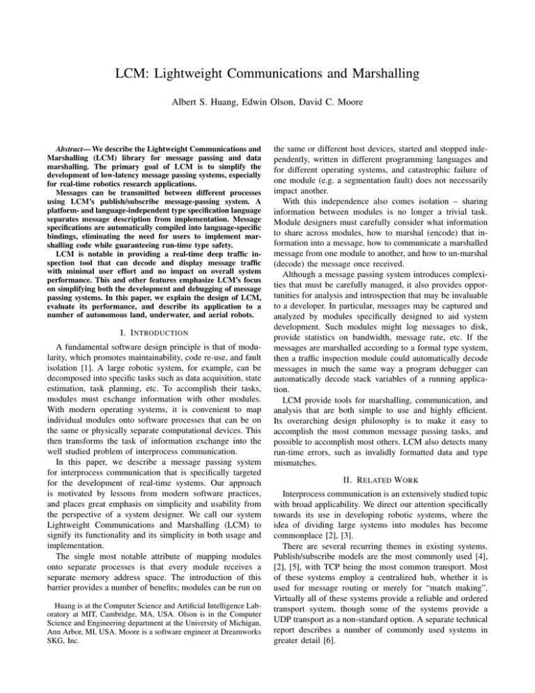
One way to measure the interprocess communication performance of LCM is by examining its bandwidth, latency,
and message loss under various conditions. Figs. 4 and 5
show a comparison of the C and Java implementations of
LCM with IPC and the ROS TCP transport.
In this test, a source node transmits fixed-size messages
at various rates. One, two, or four client nodes subscribe to
these messages and immediately retransmit (echo) them once
received. The source node measures how many messages
are successfully echoed, the round-trip time for each echoed
message, and the bandwidth consumed by the original transmission and the echoes. For this test, IPC was run in two
modes, one in which the central dispatching server relays
all data (the IPC default), and another in which the central
server acts merely as a “match maker” facilitating peer-topeer connections (central -c). To improve performance,
operating system send and receive buffers were increased to
2MB. The ROS test was implemented using ROS Box Turtle,
with TCP NODELAY set and two different maximum queue
lengths to trade off message loss and latency.
To collect each data point, the sender transmits 100MB of
data split into 800 byte messages at a fixed rate determined
by a target transmission bandwidth. Figs. 4 and 5 show
the results for tests conducted on an eight-core workstation
running Ubuntu 9.04. Hosting each process on separate
identical workstations connected via 1000Base-T Ethernet
yielded similar results. In some cases, the actual message
transmission rate does not match the target transmission rate
due to transport and software limitations.
From these figures, we can see that LCM scales with both
the amount of traffic to be sent and the number of subscribers. As network capacities are reached, LCM minimizes
latency and maintains high bandwidth by dropping messages.
The LCM Java implementation performs comparably to the
C implementation, and responds to computational limits of
the virtual machine by dropping more messages.
IPC performs well with one subscriber, but does not scale
as well to multiple subscribers as a result of transmitting
multiple copies of each message.2 Using the match-making
service of IPC (central -c) improves bandwidth and
reduces latency, but ultimately has the same difficulties.
We note that although IPC with peer-to-peer connections
maintains low latency as the attempted transmission rate is
increased, the actual bandwidth achieved does not increase
due to link saturation from duplicated messages. For example, with four clients echoing messages, IPC is unable to
transmit faster than 11 MB/s, as the bandwidth consumed
by the quadruplicate transmission and the echoes saturates
the link capacity.
The ROS TCP transport achieves high throughput when
the maximum queue length (q) is set to infinity, but at the
expense of message latency. Various settings of q provide
an adjustable tradeoff between throughput and latency. With
q = 100, message latency is on par with LCM at higher data
rates, but message loss is more frequent due to filled buffers.
A. Marshalling Performance
In addition to performance of the communications system,
we are also interested in the computational efficiency of
the LCM marshalling and unmarshalling implementations.
Performance of a marshalling system is a function of the
complexity and nature of the message, and the presence of
arrays, nested types, strings, and other fields are all factors.
We compared the performance of LCM, IPC, and ROS on
2 Our
initial experiments with IPC, using Carmen 0.7.4-beta, produced
much worse results due to coarse-grained timing functions in IPC that
degrade performance when packet rates exceed ∼1 kHz. We improved this
performance by exporting higher-resolution versions of those functions; this
improved data is used in this paper.
Fig. 6. Marshalling performance for four different marshalling implementations on three different types. Smaller numbers are better.
three common message types – a 640x480 grayscale camera
image, a single scan of a planar laser range scanner with 180
range measurements, and a list of 50 waypoints. The LCM
types in Fig. 1 are used for the waypoint list; the LCM types
for the image and laser scan messages are:
struct image_t {
int64_t utime ;
int32_t width ;
int32_t height ;
int32_t pixelformat ;
int32_t size ;
byte data [ size ] ;
}
struct laser_t {
int64_t utime ;
int32_t nranges ;
float
ranges [ nranges ] ;
float
rad0 ;
float
radstep ;
}
Similar message types were defined for IPC and ROS. In
this test, we estimate the amount of time each implementation spends encoding and decoding a single message by
averaging over the time taken to encode and decode 106
messages. Estimates were taken 10 times and then averaged.
Timings are shown in Fig. 6.
The LCM C implementation was the fastest on the path t
and image t messages, and the ROS C++ implementation
was the fastest on the laser t message. The little-endian
assumption made by ROS yields faster performance when
handling messages with many multi-byte primitive types on
little-endian computers. The pure Java LCM implementation
is generally competitive but slower handling endianness
(laser t) and large memory allocations (image t). Carmen,
despite being written in C, is fairly slow due to not using
faster block copy operations when possible.
Finally, it should be noted that the communication and
marshalling comparisons given here consider only a few
common scenarios. Performance may vary with packet size,
transmit rate, message structure, etc. Each messaging implementation can often be adjusted to various degrees, based
on the messaging and system requirements. However, these
comparisons do serve to provide some insight into the overall
performance of each system.
V. C ASE S TUDIES
Since its development, LCM has been used as the primary
communications system for a number of robotics research
platforms operating in real environments. Here, we describe
some examples of how LCM was used to assist the development of a robotics research system.
A. Urban Challenge
The 2007 DARPA Urban Challenge was an autonomous
vehicle race designed to stimulate research and public interest in autonomous land vehicle technology. Vehicles were
required to safely navigate a 90 km race course through a
suburban environment in the presence of both robotic- and
human-driven vehicles. LCM served as the communications
backbone for the Ford/IVS and MIT teams [11]. On the
MIT vehicle, 70 separate modules were simultaneously active, spread across 10 networked workstations. The average
bandwidth used by the entire LCM network was 16.6 MB/s,
with an average transmission rate of 6,775 messages/s.
Messages ranged from very small updates to camera
images and obstacle maps up to several megabytes in size.
Some, such as the pose estimates, were subscribed to by
virtually every module on the network, while others had only
one or two subscribers.
Throughout the development process, almost 100 different
message types were used, many of which changed frequently
as the capabilities and requirements of each module evolved.
Software development was distributed across many people
working from different locations, and the LCM type definitions became a convenient place for developers to agree on
how modules would interface.
Because language-specific bindings could be generated automatically from LCM type definitions, modifying messages
and the modules that used them to add or remove fields could
often be accomplished in the span of minutes. Additionally,
the runtime type checking of LCM fingerprints provided a
fast and reliable way to detect modules that had not been
recompiled to use the newly modified form of a message.
B. Land, Underwater, and Aerial Robots
Since the Urban Challenge, LCM has been applied to
a number of other robot research platforms such as small
indoor wheeled robots, arm manipulators, quadrotor helicopters [12], and an autonomous forklift [13]. In many cases,
modules used in one system were easily transitioned to others
by ensuring that the LCM messages they needed for correct
operation were present on the target robot.
In one underwater multi-vehicle research project [14],
each vehicle contains on-board sensors, thrusters, and a
computer for data processing and vehicle control. Despite
a significantly different application domain from the Urban
Challenge, the software engineering principles remain identical, and LCM has proved just as useful. New message
types are easily defined as needed, and software modules
are adapted to operate in different domains.
VI. C ONCLUSION
We have presented LCM and its design principles. LCM
is driven by an emphasis on simplicity and a focus on the
entire development process of a robotic software system. In
addition to achieving high performance, LCM also provides
tools for traffic inspection and analysis that give a developer
powerful and convenient insight into the state of the robotic
system.
The LCM type specification language is designed to allow
flexible and intuitive descriptions of a wide class of data
structures. Type fingerprints allow for runtime type checking and identification, and automatically generated language
bindings result in a simple and consistent API for manipulating messages and the data they represent. Native support
for multiple platforms and languages allows developers to
choose the environment most suitable for the task at hand.
LCM has been used as the core communications infrastructure on a number of demanding robotic systems on land,
water, and air. In each of these cases, the simplicity and versatility of LCM allowed for rapid development of complex
software systems. The modular nature of these systems has
allowed for significant code re-usability and application of
modules developed from one system to another.
LCM is distributed at http://lcm.googlecode.
com. It is supported on Microsoft Windows XP/Vista/7 and
all POSIX.1-2001 compliant platforms (GNU/Linux, OS/X,
FreeBSD, etc.)
R EFERENCES
[1] D. L. Parnas, “On the criteria to be used in decomposing systems into
modules,” Commun. ACM, vol. 15, no. 12, pp. 1053–1058, 1972.
[2] M. Montemerlo, N. Roy, and S. Thrun, “Perspectives on standardization in mobile robot programming: The carnegie mellon navigation
(carmen) toolkit,” in Proc. Int. Conf. on Intelligent Robots and Systems,
vol. 3, Las Vegas, NV, USA, October 2003, pp. 2436–2441.
[3] Willow Garage, “Robot Operating System,” http://www.ros.org.
[4] P. M. Newman, “MOOS - mission orientated operating suite,” Massachusetts Institute of Technology, Tech. Rep. 2299/08, 2008.
[5] R. Simmons and D. James, Inter-Process Communication, Aug. 2001.
[6] A. S. Huang, E. Olson, and D. Moore, “Lightweight communications
and marshalling for low latency interprocess communication,” Massachusetts Institute of Technology, Tech. Rep. MIT-CSAIL-TR-2009041, 2009.
[7] J. W. Group, The Joint Architecture for Unmanned Systems: Reference
Architecture Specification, June 2007.
[8] R. Srinivasan, “XDR: external data representation standard,”
http://www.rfc-editor.org/rfc/rfc1832.txt, Internet Engineering Task
Force, RFC 1832, Aug. 1995.
[9] T. H. Collet, B. A. MacDonald, and B. P. Gerkey, “Player 2.0: Toward
a practical robot programming framework,” in Proc. Australasian
Conf. on Robotics and Automation, Sydney, Australia, Dec. 2005.
[10] Sun Microsystems, “NFS: network file system protocol specification,” http://www.rfc-editor.org/rfc/rfc1094.txt, Internet Engineering
Task Force, RFC 1094, Mar. 1989.
[11] J. Leonard et al., “A perception-driven autonomous vehicle,” Journal
of Field Robotics, vol. 25, no. 10, pp. 727–774, Oct 2008.
[12] M. Achtelik, A. Bachrach, R. He, S. Prentice, and N. Roy, “Stereo
vision and laser odometry for autonomous helicopters in GPS-denied
indoor environments,” G. R. Gerhart, D. W. Gage, and C. M. Shoemaker, Eds., vol. 7332, no. 1. SPIE, 2009, p. 733219.
[13] S. Teller et al., “A voice-commandable robotic forklift working alongside humans in minimally-prepared outdoor environments,” in Proc.
Int. Conf. Robotics and Automation, Anchorage, AL, USA, May 2010.
[14] H. C. Brown, A. Kim, and R. M. Eustice, “An overview of autonomous
underwater vehicle research and testbed at PeRL,” Marine Technology
Society Journal, 2009.
