Estimation Of frequency Response using Millers Theorem
advertisement

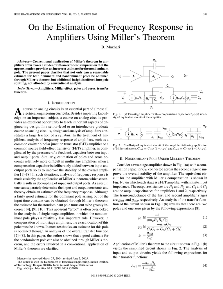
IEEE TRANSACTIONS ON EDUCATION, VOL. 48, NO. 3, AUGUST 2005 559 On the Estimation of Frequency Response in Amplifiers Using Miller’s Theorem B. Mazhari Abstract—Conventional application of Miller’s theorem in amplifiers often leaves a student with an erroneous impression that the approximation provides an incorrect estimate for the nondominant pole. The present paper clarifies that not only can a reasonable estimate for both dominant and nondominant poles be obtained through Miller’s theorem but additional insight is offered into pole splitting, not afforded by conventional analysis. Index Terms—Amplifiers, Miller effect, poles and zeros, transfer function. I. INTRODUCTION A course on analog circuits is an essential part of almost all electrical engineering curricula. Besides imparting knowledge on an important subject, a course on analog circuits provides an excellent opportunity to teach important aspects of engineering design. In a senior-level or an introductory graduate course on analog circuits, design and analysis of amplifiers constitutes a large fraction of a syllabus. In the treatment of amplifiers, analysis of frequency response of amplifiers, such as a common emitter bipolar junction transistor (BJT) amplifier or a common source field-effect transistor (FET) amplifier, is complicated by the presence of a feedback capacitor between input and output ports. Similarly, estimation of poles and zeros becomes relatively more difficult in multistage amplifiers when a compensation capacitor is deliberately added between input and output ports so as to improve the stability of the overall amplifier [1]–[8]. In such situations, analysis of frequency response is made easier by the application of Miller’s theorem, which essentially results in decoupling of input and output ports. As a result, one can separately determine the input and output constants and thereby obtain an estimate of the frequency response. Although a fairly good estimate for the dominant pole arising out of the input time constant can be obtained through Miller’s theorem, the estimate for the nondominant pole turns out to be grossly incorrect [4], [9], [10]. This apparent “error” is often overlooked in the analysis of single-stage amplifiers in which the nondominant pole plays a relatively less important role. However, in compensation of multistage amplifiers, the exact location of this pole must be known. In most textbooks, an estimate for this pole is obtained through an analysis of the overall transfer function [2]–[8]. In this paper, the author shows that a good estimate for the nondominant pole can also be obtained through Miller’s theorem, and the errors involved in a conventional application of Miller’s theorem are clarified. Manuscript received March 27, 2004; revised June 3, 2005. The author is with the Department of Electrical Engineering, Indian Institute of Technology, Kanpur 208016, India (e-mail: baquer@iitk.ac.in). Digital Object Identifier 10.1109/TE.2005.853070 Fig. 1. (a) Two-stage amplifier with a compensation capacitor C ; (b) smallsignal equivalent circuit of the amplifier. Fig. 2. Small-signal equivalent circuit of the amplifier following application of Miller’s theorem. C =C (1 A ) and C =C (1 1=A ). 2 0 2 0 II. NONDOMINANT POLE UNDER MILLER’S THEOREM Consider a two-stage amplifier shown in Fig. 1(a) with a comconnected across the second stage to impensation capacitor prove the overall stability of the amplifier. The equivalent circuit for the amplifier with Miller’s compensation is shown in Fig. 1(b) in which each stage is a FET amplifier with infinite input and , and and impedance. The output resistances are are the output capacitances for amplifiers 1 and 2, respectively. The transconductance of the first and second amplifier stages and , respectively. An analysis of the transfer funcare tion of the circuit shown in Fig. 1(b) reveals that there are two poles and one zero given by the following expressions [8]: (1) (2) (3) Application of Miller’s theorem to the circuit shown in Fig. 1(b) yields the simplified circuit shown in Fig. 2. The analysis of input and output circuits yields the following expressions for their transfer functions: 0018-9359/$20.00 © 2005 IEEE (4) 560 IEEE TRANSACTIONS ON EDUCATION, VOL. 48, NO. 3, AUGUST 2005 TABLE I COMPARISON OF VALUES OF POLES AND ZEROS OBTAINED THROUGH EXACT ANALYSIS OF THE TRANSFER FUNCTION AND THROUGH THE CONVENTIONAL METHOD USING MILLER’S APPROXIMATION. RESULTS SHOWN ARE FOR THE FOLLOWING PARAMETERS FOR THE CIRCUIT SHOWN IN FIG. 1: R = R = 10 ; C = 1 pF; C = 0.5 pF; C = 0.1 pF; AND g = g = 100 A=V (5) (6) TABLE II VALUES OF POLES AND ZEROS IN THE TRANSFER FUNCTION OF THE FIRST AND SECOND AMPLIFIER STAGES OBTAINED THROUGH (8) AND (14) AND (15). RESULTS SHOWN ARE FOR CIRCUIT PARAMETERS IDENTICAL TO THAT DESCRIBED IN TABLE I (7) Substitution of the low-frequency gain expression of in (6)–(7) shows that and are independent of “ ” and thus can be interpreted as poles associated with input and output circuits, respectively. Table I shows a comparison of these poles with those obtained through exact analysis of the agrees well with the dominant transfer function. Although lies at a frequency pole predicted by exact analysis, pole that is lower than by almost an order of magnitude. The close agreement between and on one hand and the large differcan easily lead to an impression that ence between and analysis using Miller’s theorem works well at the input stage but gives incorrect results for the output stage. However, this conobtained from Miller’s analysis clusion is not true, and pole is indeed present in the transfer function of the output stage. A complete analysis gives the following expression for the transfer function of the output stage: more accurate expression for transfer function of the first gain stage to be written, as follows: (10) (11) (12) Using dominant pole approximation [8], the denominator of (10) can be expressed as (13) (8) Equation (13) along with (10)–(12) can be used to obtain an and , as follows: estimate for poles A comparison of (8) with (5) shows that the only error that results from use of Miller’s theorem at the output stage is that is neglected in the approximation. The reason for a zero the apparent “discrepancy” between results obtained from the application of Miller’s theorem and exact analysis is that frequency-dependent characteristics of the gain associated with the output stage is neglected during evaluation of transfer func, the fretion of the first stage. If instead of quency-dependent gain expression given by (5) with is substituted in (6), one obtains a more ac, as follows: curate expression for (14) (9) can no longer be interpreted as a pole since However, it is a function of frequency. Substitution of (9) in (4) allows a (15) The complete transfer function of the first stage can now be expressed as (16) Equation (16) shows that a more accurate application of Miller’s theorem predicts the presence of one additional pole ( ) and ) in the transfer function of the first gain stage bea zero ( sides the dominant pole predicted by conventional analysis. Table II summarizes the values of poles and zeros in the transfer function of first and second stages. A comparison with values lies at a frequency shown in Table I shows that the new pole MAZHARI: FREQUENCY RESPONSE IN AMPLIFIERS USING MILLER’S THEOREM 561 . nected in parallel to a resistor of value Since this resistor value is often much smaller than resistor , the input stage can be effectively modeled as this resistor con, thereby giving rise to nected in parallel to capacitor the expression (15) for nondominant pole. The only source of error in analysis using Miller’s approximation described previously arises from the neglect of a zero in the transfer function of the second amplifier stage (or the output circuit in single amplifier stages). If (8) is used instead of (5) in obtaining (15), one matches with pole , obtained through analfinds that pole ysis of the complete transfer function. III. CONCLUSION Fig. 3. Gain of the first stage (A ), second stage (A ), and overall amplifier (A ) as a function of frequency. The results were obtained through simulation of the circuit shown in Fig. 1(b) for the following parameters: R = R = 10 ; C = 1 pF; C = 0.5 pF; C = 0.1 pF; and g = g = 100 A=V. close to the nondominant pole , estimated through exact analysis of the transfer function. Furthermore, the zero in the transfer function of the first stage lies at the same frequency as pole in the transfer function of the second stage, resulting in a mutual cancellation of their effect on the overall transfer function. The poles and zeros in the transfer function of the first and second stages can also be clearly seen in Fig. 3 which shows the variation of gain with frequency for the first and second amplifier stages and also shows the frequency response of the overall amplifier obtained through simulation of the circuit shown in Fig. 1(b). The transfer function of the first stage has two poles and a zero; the latter matches with the pole in the transfer function of the second stage. As a result, the overall transfer funcand and a zero at tion reveals presence of only poles higher frequencies. The physical reason for pole–zero cancellation is that when the gain of the second stage begins to reduce , the effective capacitance with frequency because of pole seen by the first stage also begins to reduce. This because of reduction stops the 20-dB/decade decrease in gain of the first stage and makes it constant. As a result, the overall gain is unaffected and continues to roll off at 20 dB/decade only as seen in Fig. 3. The nondominant pole can also be understood in terms ) because of the compensation of the effective impedance ( capacitor seen by the first stage, as follows: (17) At frequencies much higher than duces to To summarize, an estimate for both dominant and nondominant poles in an amplifier’s transfer function can be correctly obtained from application of Miller’s theorem, provided that the expression used for voltage gain in obtaining Miller’s capacitance includes frequency response of the gain as well. Conventional use of Miller’s theorem does not commit an error by incorrectly predicting the value of pole in the transfer function of the second stage, but rather commits an error of omission by failing to predict a zero at the exact location of this pole and an additional nondominant pole in the transfer function of the input stage. The analysis using Miller’s theorem provides the insight that a process of pole–zero cancellation is involved in the well known pole-splitting effect of compensation capacitor. REFERENCES [1] J. Millman and A. Grabel, Microelectronics. New York: McGraw-Hill, 1987. [2] P. R. Gray, P. J. Hurst, S. H. Lewis, and R. G. Meyer, Analysis and Design of Analog Integrated Circuits, 4th ed, Singapore: Wiley, 2001. [3] R. T. Howe and C. G. Sodini, Microelectronics—An Integrated Approach. Englewood Cliffs, NJ: Prentice-Hall, 1997. [4] M. N. Horenstein, Microelectronic Circuits and Devices, 2nd ed. Englewood Cliffs, NJ: Prentice-Hall, 1996. [5] A. S. Sedra and K. C. Smith, Microelectronic Circuits, 4th ed. New York: Oxford, 1997. [6] P. E. Allen and D. R. Holberg, CMOS Analog Circuit Design. New York: Oxford, 2002. [7] R. J. Baker, H. W. Li, and D. E. Boyce, CMOS Circuit Design, Layout, and Simulation. New York: Wiley-IEEE Press, 1997. [8] D. A. Johns and K. Martin, Analog Integrated Circuit Design. New York: Wiley, 2002. [9] A. Filipkowski, “Poles and zeros in transistor amplifiers introduced by Miller effect,” IEEE Trans. Educ., vol. 31, no. 4, pp. 349–351, Nov. 1999. [10] W. H. Ki, L. Der, and S. Lam, “Re-examination of pole splitting of a generic single stage amplifier,” IEEE Trans. Circuits Syst., vol. 44, no. 1, pp. 70–74, Jan. 1997. , the above expression re- (18) Equation (18) shows that at high frequencies, the compensacontion capacitor appears to the input stage as a capacitor B. Mazhari received the B.Tech. degree in electronics and electrical communication engineering from the Indian Institute of Technology (IIT) Kharagpur, Kanpur, India, in 1987 and the Ph.D. degree in electrical engineering from the University of Illinois at Urbana Champaign in 1993. He is currently an Associate Professor with the Department of Electrical Engineering, IIT. His research interests include semiconductor device modeling, analog circuit design, and organic electronics.


