PIR and MW outdoor detector instructions
advertisement

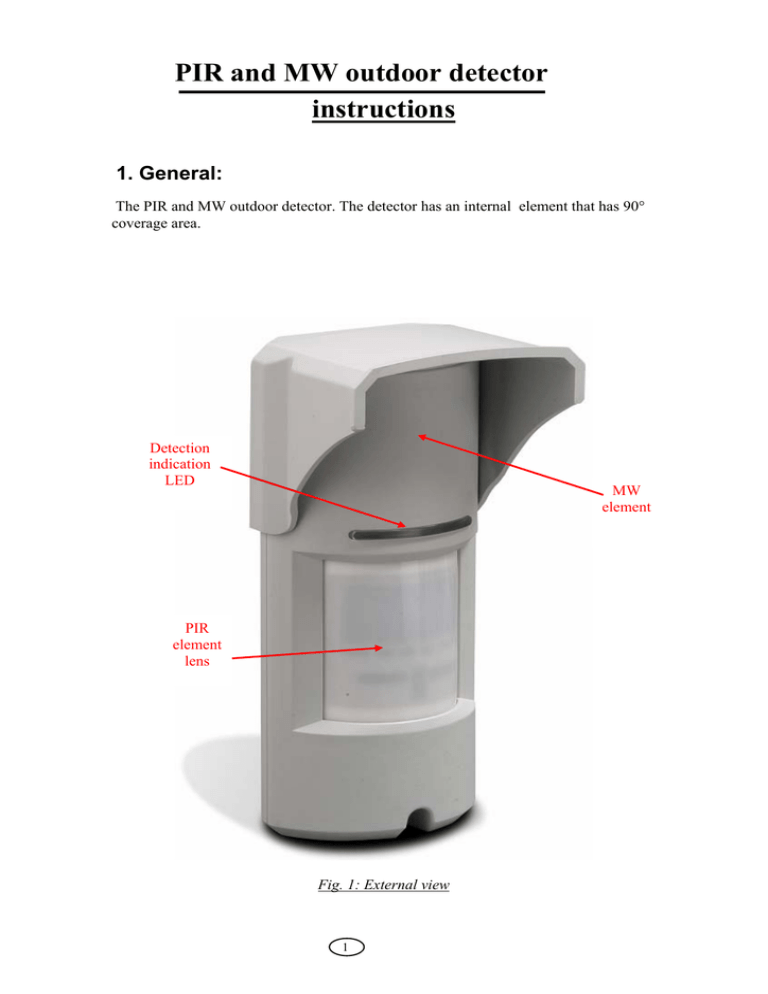
PIR and MW outdoor detector instructions 1. General: The PIR and MW outdoor detector. The detector has an internal element that has 90° coverage area. Detection indication LED MW element PIR element lens Fig. 1: External view 1 MW element Indication LEDS LED control MW Sensitivity adjust PIR element Tamper switch PIR Sensitivity adjust Terminal Block Fig. 2: Internal view Fig. 3: Detection Pattern – Top view 2 6 2 Detector Installation Important! Prior to installation, read both “Operation” and “Selecting the mounting location” sections carefully. 1. Install the detector in such manner that the intruder is 2. The detector is to be installed at height of 1.8 to 2.4 most likely to cross the detection area from side to side. meters (5.9 to 7.9 ft) Fig 4:Detection patten-side view 3. Make sure to attach the metal bracket to a leveled 4. Placing the detector on perpendicular wall is straight and firm wall, leaving 10cm (4 inches) from the required for guarding a side window opening. top and 10cm (4 inches) from both sides, for easy installation and maintenance. 5. Open the detector unwinding the bottom screw. 6. Release the rear metal bracket by unwinding internal bottom screw. 3 7. Release the detector body from the metal bracket by 8. Attach the rear bracket to the wall using mounting pulling to front and up. screws or metal bands. Fig 5:Rear bracket 9. Slide the wires from the rear side internally. 10. Attach the sealing sponge pad to the wire opening from the rear side after the wires connection and prior to final product affixing to the mounted bracket. 11. Place the detector on the mounting bracket from top 12. Select relevant PET immunity level by side down and then lock the screw at the bottom. disassembling PET filter (supplied and assembled) or using the filter. (Refer to paragraph 8.3 for more details) Fig 6: Metal-Band usage 4 Using the mounting bracket, the Detector is to be installed according to the following drawing: Fig. 7: Installation height 3.Sensitivity adjustment: The PIR sensitivity is determined by an internal potentiometer, which controls an analogue parameter inverted to digital one and sets the sensitivity by adaptive signal. Changing the sensitivity affects immunity to environmental noises and also affects the detection distance. Fig. 8: PIR Sensitivity Adjust 5 In addition, there is an option to control the MW sensitivity by means of jumper, between “H” (high) and “L” (low) options. Fig. 9: MW Sensitivity Selection 4.Installer setup options: The installer has an option to control LEDs operation, using the LED control jumper, between “ON” and “OFF”. The Green LED indicates PIR detection, the Yellow LED indicates MW detection and the Red LED - alarm indication (logic AND of both MW and PIR). Red LED: Alarm Indication Green LED: PIR Detection Fig. 10: LED Indications Fig. 11: LEDs Control 6 Yellow LED: MW Detection 5. The Detector has an optional PET Immunity filter that can be assembled inside the product. Pet Immunity Filter Fig. 12: PET Immunity Filter and cover Fig. 12: PET Immunity Filter assembled 7 6.Technical Specifications: Detection Method Power Input Current Draw Temp Compensation Alarm Period Alarm Outputs Tamper Switch(s) Warm up Period LED Indicator RF Immunity ElectroStatic Immunity Transient Immunity Operation Temp Dimensions Weight PIR AND MW 9.6 to 16Vdc Active: 24mA (±5%) Standby: 21mA (±5%) Yes, Dual slop temperature compensation 2 sec (±0.5sec) NC NO Common End Of Line 28Vdc 0.1 A with 10 Ohm Two Switches N.C 28Vdc 0.1 A with 10 Ohm Series protection resistors Open when cover or base are removed 60sec (± 5sec) All LEDs are ON during ALARM 10 V/m plus 80% AM from 80 MHz to 2GHz 6kV contact, 8kV air 1kV -10ºC ~ +50 ºC 175mm x 70mm x 45mm 210gr. End of Document 8


