An Improved MTL Modeling of Transformer Winding
advertisement

An Improved MTL Modeling of Transformer Winding S.M.H. Hosseini, M. Vakilian, G.B. Gharehpetian Abstract­­ This paper presents a new approach for modeling of the windings using Multi­conductor Transmission Line (MTL) theory. In this model loss factor coefficient ( tan δ ) and dielectric constant ( ε ) have been considered as frequency dependent parameters. The improved multi­conductor transmission line (MTL) theory has been employed to model a 900 MVA, 500 kV transformer windings. It is shown that the simulation result of model with frequency dependent loss factor has a good agreement with measurements results. Keywords: Transformer winding, Fast transient, Multi­ conductor transmission line, Loss factor. I. INTRODUCTION F
ast transient overvoltages can occur in transformers, in a high frequency range which can extend to 1 MHz. One of the most suitable and feasible stages for evaluation of such phenomena by simulation of the transformer winding model, is the design stage. Using this model, a proper insulation design can be suggested and the risk of occurrence of overvoltages at the resonance frequencies can be minimized. The existing transient transformer models [1­3] can be categorized as: "Detailed lumped parameters Model" or "Multi­conductor Transmission Line (MTL) Model". The fundamental elements of the detailed model are the lumped RLC circuit elements. The upper frequency range for the validity of this model is few hundred kHz [2­4]. In order to extend this range to a few MHz, it is necessary to use a turn­ to­turn modeling procedure instead of disk­to­disk modeling [4]. This procedure will result in a large scale system. It is difficult to simulate and to analyze such a sophisticated system especially in a reasonable time. there is no detailed information available on some parts of winding which is included in the black box model. To overcome the above mentioned problems, the method of this paper has been proposed which is based on distributed parameter transmission line (MTL) theory. Using this method, the number of equations and the size of memory required for calculation of transient responses decreased significantly. The proposed MTL model has frequency dependent parameters. Although frequency dependent modeling of transformer is discussed in the literature, however most of them are focused on the lumped parameters model. The published works on MTL modeling is mostly concentrated on modeling electrical machines [5­6] and also on transformer windings [3], [7­8], ignoring the frequency dependence of the parameters.
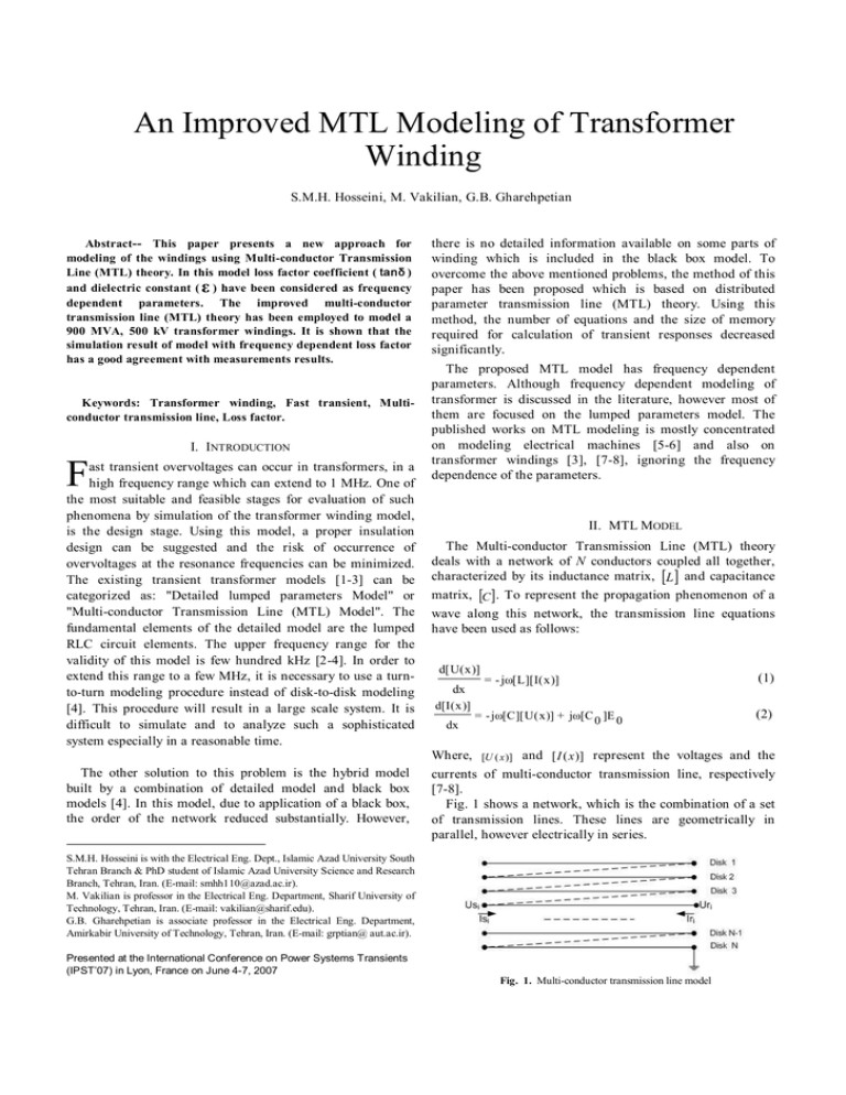
II. MTL MODEL The Multi­conductor Transmission Line (MTL) theory deals with a network of N conductors coupled all together, characterized by its inductance matrix, [L ] and capacitance matrix, [C ] . To represent the propagation phenomenon of a wave along this network, the transmission line equations have been used as follows: d [ U ( x )] dx d [ I ( x )] dx = ­ j ω [ C ][ U ( x )] + j ω [ C 0 ]E 0 Where, The other solution to this problem is the hybrid model built by a combination of detailed model and black box models [4]. In this model, due to application of a black box, the order of the network reduced substantially. However, = ­ j ω [ L ][ I ( x )] (1) (2) and [ I ( x )] represent the voltages and the currents of multi­conductor transmission line, respectively [7­8]. Fig. 1 shows a network, which is the combination of a set of transmission lines. These lines are geometrically in parallel, however electrically in series. [ U ( x )] S.M.H. Hosseini is with the Electrical Eng. Dept., Islamic Azad University South Tehran Branch & PhD student of Islamic Azad University Science and Research Branch, Tehran, Iran. (E­mail: smhh110@azad.ac.ir). M. Vakilian is professor in the Electrical Eng. Department, Sharif University of Technology, Tehran, Iran. (E­mail: vakilian@sharif.edu). G.B. Gharehpetian is associate professor in the Electrical Eng. Department, Amirkabir University of Technology, Tehran, Iran. (E­mail: grptian@ aut.ac.ir). Presented at the International Conference on Power Systems Transients (IPST’07) in Lyon, France on June 4­7, 2007 Fig. 1. Multi­conductor transmission line model As it can be seen in this figure, we have: Ir i = Is i + 1 (3) Ur i = Us i + 1 (4) Now two different modeling techniques may be used: a. To model each disk with a multi­conductor transmission line, and making this equivalent to the model in which each turn is modeled as an extended transmission line. b. To model each disk in form of an extended single­ conductor line. U ( x ) = kE 0 + A exp( ­ Γ ( ω ) x ) + B exp( Γ ( ω ) x ) (9) I ( x ) = ( 1 / z ) { A exp( ­ Γ ( ω ) x ) ­ B exp( Γ ( ω ) x ) } (10) Where: z i : Surge impedances and Γ : Coefficient of propagation can be estimated by comparison of these two models. The following equations are the result of this comparison [7­10]. z i = In each of those, the required parameters, such as: surge impedance and propagation coefficient, can be estimated [7­8], [10­12]. 1 ωa i i ν s [C + C + 2K{1 ­ cos( )}] 0 1 ν s 1 ω ω tan δ (11) j ω In first step, the turns in each disk should be modeled with equivalent transmission lines. Assume that a sinusoidal power supply with the amplitude of E 0 and angular frequency of w is connected to the input of Γ = the above model. Solving the equations (1) and (2) results in: An algorithm has been developed in [7] which can model the disks of a winding by a single­conductor transmission line and then the overvoltages between the disks can be determined. Using these results, any arbitrary disk can be selected and modeled by a multi­conductor transmission line and then the overvoltages between the turns can be calculated. U i ( x ) = k E 0 + A i exp( ­ Γ ( ω ) x ) + B i exp( Γ ( ω ) x ) i (5) I i ( x ) = ( 1 / z i ){ A i exp( ­ Γ ( ω ) x ) ­ B exp( Γ ( ω ) x )} i (6) The coefficients, A i and B i , are the value of surge voltages amplitudes at the sending and receiving ends which can be ν s d 2 σμ + 2 ν s + ν s (12) III. FREQUENCY DEPENDENCE LOSS FACTOR AND DIELECTRIC CONSTANT determined from boundary conditions. k i is the ratios of Both, the dielectric constant and the dielectric loss factor in electrostatic induced voltages and G is the propagation the oil treated cellulose papers are affected by the change of coefficient. the test voltage frequency. The dielectric constant when Velocity of the electromagnetic wave in the insulator is: measured at lower permissible test temperature, demonstrates its highest variation as the test frequency increases. Figures 2 c (7) and 3 illustrate this variation for the loss factor and the ν s = ε r dielectric constant of the oil impregnated cellulose at different temperatures over the frequency range of less than one [ C ] ­1 megacycle per second [12]. (8) [ L ] = ν s 2
As it can be seen in these figures, the dielectric constant remains approximately unchanged however the dielectric loss Where, c is the light speed in vacuum and e r is the o factor varies versus frequency. At 46 C , the dielectric insulator relative dielectric constant. The detailed definitions constant is about 2.5 even when frequency changes from 0 to of the distributed parameters are given in [12]. 1 MHz. At the same temperature, the loss factor can be estimated to be 0.006 in the frequency band of 0­40 kHz and In second step, disks are modeled by a single­conductor then it increases linearly with frequency and at 1 MHz it is transmission line and a set of similar equations derived as equal to 0.036 [12].
follows [7­10]: Fig. 4. Variation of tan d versus frequency Fig. 2. Loss factor of oil impregnated cellulose versus frequency TABLE I Technical specifications of IPC transformer windings Parameters related to surge Disc date propagation Dielectric constant of insulation Number of discs m=12 e r =2.65 Turn length Surge velocity ( i ) u s = 184 m / m s a =6.83 m Dielectric loss factor 1. tan d = 0.02 Constant 2. tan d Variant versus f Disc turns ( i ) N =17 , 17 , 21 , 21, 23 , 23 , 23 , 23 , 21 , 21 , 17 , 17 Fig. 3. Dielectric constant of oil impregnated cellulose versus frequency Conductor conductance d = 5 ´ 10 7
s m m = m 0 = 4 p ´ 10 - 7 H m d = 3.55 mm IV. SIMULATION RESULTS The improved MTL model presented in the last section is applied to the HV winding of a 900 MVA, 500 kV transformer. The technical specifications of this transformer are given in Table I. Fig. 4 shows the frequency dependent loss factor model employed in this simulation. The transformer windings have been modeled by a set of transmission lines with frequency dependent parameters. It is assumed that a sinusoidal power supply with the amplitude of E 0 and angular frequency of w is applied to the terminal of winding. The absolute value of voltage between discs with respect to the input voltage can be determined for different type of transformer discs. Fig. 5 and Fig. 6 show inter­discs voltages for constant and frequency dependent loss factor, respectively. Fig. 7 and Fig. 8 show the same simulation results in 3dimensional graphs. Disc capacitance Disc ­ Disc Distributed capacitance parameter of coil 1 Inter­turn ( i ) ( i ) C m = 7500 p . F k =158 pF/m Conductor static plate ( 1 ) Disc ­ ground C 0 =5.7675pF/m ( i ) C g = 10 p . F ( 1 ) C 1 =64.59 pF/m V. CONCLUSIONS This paper presents an improved MTL model of transformer windings for fast transient studies. A HV winding of 500 kV, 900 MVA power transformer is modeled using the suggested model in a wide frequency range of 10 kHz to 1 MHz. Simulation results have shown that MTL model with frequency dependent loss factor can represent the fast transient behavior of HV winding better than the models with Comparing these simulation results with the constant tan δ .
measurement results of [7], it is obvious that the MTL model with frequency dependent loss factor has a better agreement with measurement results. Fig. 5. Inter­ discs voltages for constant tan d (equal to 0.02) Fig. 6 Inter­ discs voltages for frequency dependent tan d Fig. 7. 3D presentation of figure 5. Fig. 8. 3D presentation of figure 6.
VI. REFERENCES [1] P. A. Abeti, “Biliography on the surge performance of transformers and ratating machines”,AIEE Trans., pp. 1150­1168, 1958. [2] P. I. Fergastad and T. Henriksen, “A Calculation method for impulse vdtage distribution and transferred voltage in transformer windings”, IEEE Trans. Power App.Sys., pp.930­939, 1978. [3] K. Cornic, B.Filliat, C. Kieny and W. Muller, “Distribution of very fast transient overvoltages in transformer”, Cigree, pp. 12­234, 1992. [4] G.B. Gharehpetian, H. Mohseni, K. Moller,” Hybrid modeling of inhomogeneous transformer windings for very fast transient overvoltage studies”, IEEE transaction on power delivery, Vol. 13, No.1, pp 157 ­163, 1998. [5] P.G. Mclaren, and M.H. Abdel­Rahman “Modeling of large AC Motor disk for steep­fronted surge Studies”, IEEE Trans. on Industry Applications, Vol.24, No.3, pp. 422­426, 1988. [6] J.L. Guardado, and K.J Cornick, “A computer model for calculating steep­fronted surge distribution in machine windings”, IEEE Trans. on Energy Conversion, Vol.4, No.1, pp. 95­101, 1989. [7] Y.Shibuya, S.Fujita, N. Hosokawa, “Analysis of very Fast transient over voltage in transformer winding”, IEE Proc. G.T.D, Vol.144, No.5, pp. 461­468, 1997. [8] M. Popov, L.V. Sluis, G. C. Paap, “Computation of very Fast transient over voltages in transformer windings”, IEEE Trans. on Power Delivery, Vol, 18, No.4, pp, 1268­ 1274, 2003. [9] S.M.H. Hosseini, M.Vakilian and G.B. Gharehpetian,“ Modeling of IPC transformer windings for fast transient studies”, International power system transient,IPST2005, Montreal, Canada, 2005. [10] S.M.H. Hosseini, M.Vakilian and G.B. Gharehpetian, “Effect of Closing Resistance on VFTOs of IPC Transformer Windings”, ISH2005, Beijing, China, 2005. [11] Peng Ying and Ruan Jiagjum,” Investigation of very fast transient overvoltage distributed in taper winding of tesla transformer”, IEEE Transaction on Magnetics, Vol. 42, No.3, pp 434 ­441, March 2006. [12] Frank M. Clark,”Insulating materials for design and engineering practice”, John Wiley and Sons, Inc. New York, London, 1962, Vol. 1, pp. 278­323. VII. BIOGRAPHIES S.M.Hassan Hosseini was born in Tehran, Iran, in 1969. He received his B.Sc. degree in electrical power engineering from Ferdowsi University of Mashhad, in 1993. He received a M.Sc. degree in electrical power engineering from Islamic Azad University South­Tehran Branch, in 2000. From 2001 he is a Ph.D. student of Islamic Azad University Science and Research Branch, Tehran, Iran. From 1993 till now he is the hydropower electrical expert of Iran Water and Power development resources Company (IWPCO). He joined the faculty of Azad University South­Tehran Branch in 2000. Mehdi Vakilian received his BSc in electrical engineering (1978) and MSc (1986) in electric power engineering from Sharif University of Technology in Tehran.PhD in electric power engineering from Rensselaer Polytechnic Institute, Troy, NY, USA in 1993. He worked with Iran Generation and Transmission Company (Tavanir) as Manager of ransmission Network Operation Department (1981­1983), and as Director of Transmission & Distribution Education Planning Department of Iranian Ministry of Energy (1984­1985). From 1986 he joined the Faculty of Department of Electrical Engineering of Sharif University of Technology as Instructor. From 1993 he continued his work as Assistant Professor in electric power engineering; from 1997 to 2001 he was also Director of Electric Power Group. From 2001 to 2003 he was Associate Professor and also Chairman of the Department. His research interest is transient modeling of power system equipments, optimum design of high voltage equipments insulation, and insulation monitoring. During September 2003 to September 2004 he was on leave of study at School of Electrical Engineering & Tel. of University of New South Wales, Sydney, Where he concentrated his research on study of PD signals propagation in XLPE cables. At present he is also director of restructuring committee of Electrical Engineering education in Sharif University. Gevork B. Gharehpetian was born in Tehran, in 1962. He received his BS and MS degrees in electrical engineering in 1987 and 1989 from Tabriz University, Tabriz, Iran and Amirkabir University of Technology (AUT), Tehran, Iran, respectively, graduating with First Class Honors. In 1989 he joined the Electrical Engineering Department of AUT as a lecturer. He received the Ph.D. degree in electrical engineering from Tehran University, Tehran, Iran, in 1996. As a Ph.D. student he has received scholarship from DAAD (German Academic Exchange Service) from 1993 to 1996 and he was with High Voltage Institute of RWTH Aachen, Aachen, Germany. He held the position of Assistant Professor in AUT from 1997 to 2003, and has been Associate Professor since 2004. Dr. Gharehpetian is a Senior Member of Iranian Association of Electrical and Electronics Engineers (IAEEE), member of IEEE and member of central board of IAEEE. Since 2004 he is the Editor­in­Chief of the Journal of IAEEE. The power engineering group of AUT has been selected as a Center of Excellence on Power Systems in Iran since 2001. He is a member of this center since 2004. He is the author of more than 170 journal and conference papers. Since November 2005 he is the director of the industrial relation office of AUT. His teaching and research interest include power system and transformers transients, FACTS devices and HVDC transmission.


