PART TWO
of a predictive
maintenance series
Applying handheld test tools
to predictive maintenance
Unplanned downtime due to
equipment failure costs manufacturers up to 3 % of their revenue
each year. For a $1 billion manufacturer, that’s $30 million of
potential savings, directly to the
bottom line. If a company has a
net income of $100 million, that’s
a 30 % reduction in profitability.
In an era of extreme competitiveness, no one can afford to let
this kind of money slip through
their hands.
Scheduling downtime for
maintenance is much more cost
effective and efficient. Planned
downtime allows maintenance
managers to determine:
1. How to utilize their personnel,
2. If the correct spare parts are in
stock to make repairs, and
3. How to minimize the amount
of time a facility is out of operation.
The trick is figuring out what
equipment needs repair when —
otherwise downtime, technician’s
time and part costs can still get
out of hand.
Predictive maintenance (PdM)
programs regularly measure key
indicators on critical equipment
and track that information over
time, helping technicians predict
when repairs are necessary.
This application note describes
the PdM measurements you can
gather and track with DMMs,
clamp meters, digital infrared
thermometers and insulation
resistance testers. Other application notes in this series discuss
PdM applications for thermal
imagers and power quality analyzers.
Predictive maintenance
cost savings
Predictive maintenance programs
improve performance, increase
productivity, reduce downtime
hours, and lower maintenance
and inventory costs. Studies by
the Federal Energy Management
Program (FEMP), estimate predictive maintenance can save 8 %
to 12 % over routine maintenance and 30 % to 40 % over
unplanned downtime.
Application Note
Independent surveys report
the following average savings
from industrial predictive maintenance programs:
• Return on investment:
10 times
• Reduction in maintenance
costs: 25 % to 30 %
• Elimination of breakdowns:
70 % to 75 %
• Reduction in downtime:
35 % to 45 %
• Increase in production:
20 % to 25 %
Integrating tools
and programs
PdM programs vary from the
highly sophisticated, with continuous online monitoring and
automated alerts, to more traditional offline programs that rely
on inspection routes and manual
measurements.
PdM monitoring tools also vary
in complexity, from digital spot
infrared thermometers to thermal
imagers, vibration analyzers and
power quality tools, to permanently mounted and networked
sensors. Investigative tools vary
from handheld DMMs, clamp
meters, and insulation resistance
testers to specialized motor circuit
testers.
Many facilities mix and match,
depending on their equipment
and scale of operations. What’s
different is that these technicians
are repurposing tools traditionally used for troubleshooting for
predictive maintenance measurement programs.
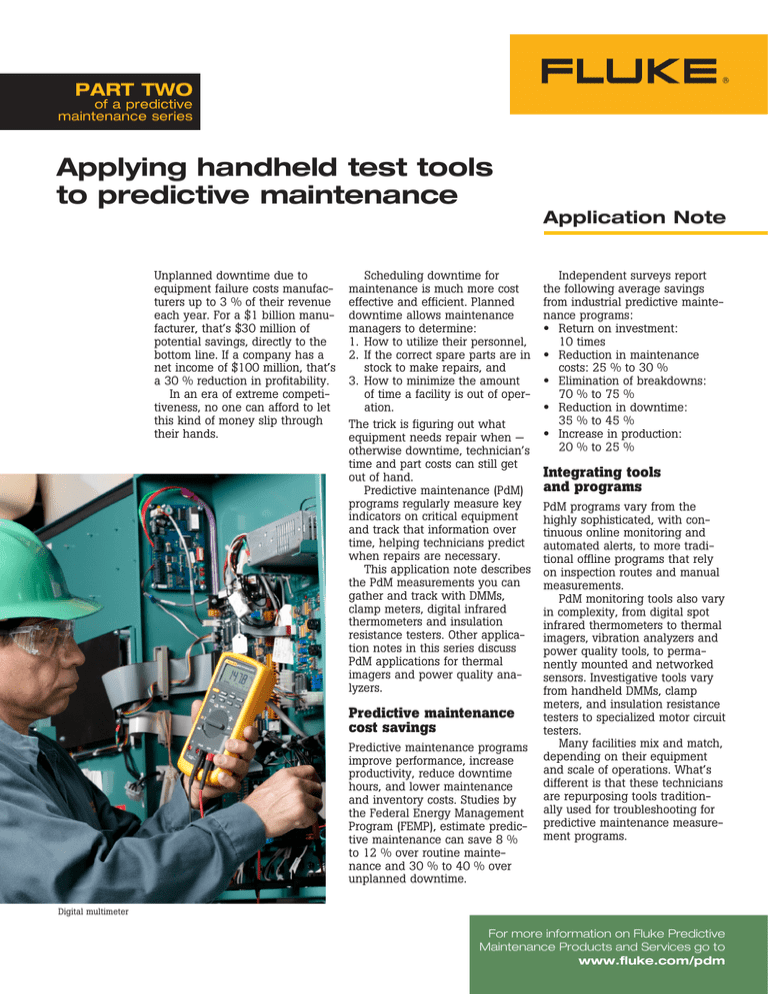
Digital multimeter
For more information on Fluke Predictive
Maintenance Products and Services go to
www.fluke.com/pdm
PdM measurements with handheld test tools
Equipment
Key Indicators
Measurement
Test Tool
UPS/PDU
– Intermittent tripping
– Process interrupts
RMS voltage, rms current, frequency (Hz), connection resistance, data log readings over time for anomalies.
IR, DMM
Transformer
– Heat
– Buzzing
Temperature, impedance at neutral-ground bond, voltage
balance, current balance, loose connections.
IR, DMM, CM
Panels/switchboards
– Intermittent tripping
– Hot circuit breakers
Voltage balance, current balance, data log readings over time for anomalies, loose connections, temperature.
IR, DMM, CM
Controls (ASDs Disconnects)
– Process anomalies
– Change in system
performance
Voltage balance, current balance, inrush current, voltage sags, connection resistance, data log readings over time
for anomalies.
IR, DMM, CM
Lighting panels
– Flickering lights
– Buzzing
Voltage balance, current balance, inrush current, voltage sags, connection resistance, data log readings over time
for anomalies.
IR, DMM, CM
Inrush current, insulation resistance to ground, temperature, IR, IRT, DMM, CM
nameplate rating, overloading, voltage balance, current
balance, resistance, connection motor start capacitor.
Motors and other equipment – Heat
(gearboxes, pumps, fans,
– Intermittent tripping
chillers, A/C units,
generators)
Key: Infrared thermometer (IR), digital multimeter (DMM), insulation resistance tester (IRT), clamp meter (CM).
Note: These recommendations are not a complete set of PdM measurements.
Measurement Guidelines
Predictive maintenance measurements aren’t that different from
troubleshooting tests. You’re
looking for signs of potential failures, so you take measurements
related to failure modes.
1. For each type of equipment,
identify the potential failures
and related key indicators.
2. Determine what measurements
can reduce the likelihood of
problems.
3. Determine how often equipment needs to be measured.
4. Collect and track the results,
watch for trends, and instigate
repairs as needed.
Temperature
Infrared thermometers are a
low-cost monitoring option for
quick, frequent measurements of
specific components while equipment is operational. Use your
knowledge of your equipment to
identify key hot spots to track,
compare those temperature readings to operational limits, and
watch for upward trends.
Fluke Corporation
For example, scan the bearing
housings on motors, the switches
in circuit breaker panels, and the
wiring connections at all equipment. For the best measurements,
get as close as is safely possible
to your target, make sure you’re
not measuring a reflective
surface, and compensate for
emissivity.
Insulation resistance
to ground
Caution: Before testing cabling
and motors, disconnect any
electronic controls — misapplication of high voltage testequipment can destroy them.
Regularly conducting the
following insulation resistance
tests on loads and connections
can help detect imminent equipment failure.
• Ground testing line and load
circuits at the starter will identify the resistance to ground of
the starter, line circuits to the
disconnect, and load lines to
the motor and starter windings.
Frontline test tools for predictive maintenance
Infrared thermometer
•
General thresholds: ac devices
can safely operate at not less
than two megohms to ground
and dc devices can safely
operate at not less than one
megohm to ground.
• When measuring the resistance of a three phase motor
between the load legs of the
starter, you should see high
resistance and roughly equivalent measurements between
phases.
A true-rms DMM is necessary
to accurately measure ac voltage affected by harmonics, and a
low-bandwidth filter is necessary
to accurately measure adjustable speed drive (ASD) voltage. A
DMM can also be used to check
for proper voltage balance in the
supply system. Logging DMMs
can be used to monitor changes
in performance over time and can
give you warning of impending
failure.
Note: Insulation resistance to ground tests
conducted with an insulation resistance tester
require disconnecting the components or
cabling to be tested from the power system
—incorporate this into planned downtime.
Resistance
Power quality
DC and AC supply voltage
It pays to regularly measure
voltage at critical equipment, to
verify the load is receiving stable
supply voltage within the nameplate rating tolerances. Too much
or too little voltage causes reliability problems and equipment
failures.
Caution: Resistance measurements must be made with the
circuit power off. Otherwise,
the meter or circuit could be
damaged.
A DMM can check the resistance across most connections.
The higher the resistance, the
more degraded the connection, a
flag for reduced voltage supply,
nuisance tripping and potential
equipment failure.
• High resolution DMMs can also
measure the resistance across
relay and circuit breaker contacts - resistance goes up as
the contacts degrade.
• IR thermometers can also
identify high resistance connections — they show up as
hot spots when compared to a
good connection.
DMM Notes: Most DMMs measure down to
0.1 W and some measure as high as 300 MW.
For accurate low-resistance measurements,
use the DMM’s REL function to eliminate test
lead resistance.
DC and AC current
Voltage balance
A greater than two percent voltage unbalance can reduce equipment performance and cause
premature failure. Use your DMM
to check voltage between phases
for voltage drops at the protection
and switchgear delivering power
from the utility and at high priority equipment.
Voltage unbalance can be
calculated with this formula.
average volts = (ph1 volts +
ph2 volts + ph3 volts) / 3
% voltage unbalance on ph1
= ((ph1 volts - average volts)
/ average volts) x 100
Note: Voltage drops across the fuses and
switches can also show up as unbalance at
the motor and excess heat at the root trouble
spot. Before you assume you’ve found the
cause, double check with a thermometer.
Current balance
Another root cause for equipment
overheating is current unbalance. Use a clampmeter or an ac
current clamp with your DMM to
check the current draw on each
of the three legs. To determine
average current, sum the current
from all three phases and divide
by three. Then, calculate the
percent unbalance by subtracting
the actual on one leg from the
average amps, then divide by the
average amps and multiply by
100. More than 10 percent current imbalance can be a
problem.
average amps = (ph1 amps +
ph2 amps + ph3 amps) / 3
Caution: After measuring cur% unbalance on ph1 = ((ph1
rent with a DMM, don’t forget
amps - average amps) /
to move test leads back to
average amps)) x 100
voltage before attempting your
next voltage measurement.
Loads will draw slightly higher
current as they age. Regularly
measuring current can help you
track equipment reliability. Use
either a clamp meter or a DMM
combined with a current clamp
for measuring current.
MegOhmMeter insulation resistance tester
Fluke Corporation
Frontline test tools for predictive maintenance
Inrush current
If a motor isn’t performing correctly or if your circuit is unexpectedly tripping, check inrush
current at startup with a clamp
meter or a DMM designed to
capture inrush current. Inrush
current can reach up to twelve
times the normal running current
— much higher than the circuit
breaker rating — without tripping
the breaker, as long as the circuit
isn’t overloaded. Evaluating your
inrush current depends on comparisons of inrush measurements
over time for that motor.
Safety and test tool rating requirements
Before you start using your DMM or other test tools for predictive
maintenance, make sure you understand the limitations of your tool
and the safety precautions that go along with it.
• Choose a DMM rated for 1000 V CAT III / 600 V CAT IV and a
clamp meter rated for 600 V CAT III.
• For DMMs, look for true-rms, resistance of 0.1 ohms or less,
capacitance test to 9999 microfarads, and frequency. If you’re
tracking data over time, get a DMM with data/event logging capabilities and fast Min/Max, sufficient memory, extended-life batteries, an optical port, and software for downloading measurement
results to your computer.
• For typical industrial and commercial motors, choose an insulation
resistance tester with a minimum of 500 V output and resistance
measurements to several gigohms.
• Determine how close you can safely stand to your equipment during temperature measurements and use that to determine what
distance-to-spot ratio your infrared thermometer must support. A
Distance-to-spot size ratio of 50:1 allows accurate measurement
within 8 feet, depending on target object emissivity.
• Ensure the voltage rating on your test probes matches your test
environment. Insulation resistance testing typically requires high
voltage probes, as do some DMM tests.
• If you must make live measurements in a three phase environment, wear the appropriate Personal Protective Equipment (PPE),
use the three point test method, and if possible, keep one hand
in your pocket to prevent current transfer.
Three-point test method:
1. Test a known live circuit.
2. Test the target circuit.
3. Test the live circuit again.
This verifies that your meter worked properly before and after the
measurement, and ensures you know whether a circuit is live.
Clamp meter
Fluke.Keeping your world
up and running.®
Fluke Corporation
PO Box 9090, Everett, WA USA 98206
Fluke Europe B.V.
PO Box 1186, 5602 BD
Eindhoven, The Netherlands
For more information call:
In the U.S.A. (800) 443-5853 or
Fax (425) 446-5116
In Europe/M-East/Africa +31 (0) 40 2675 200 or
Fax +31 (0) 40 2675 222
In Canada (800)-36-FLUKE or
Fax (905) 890-6866
From other countries +1 (425) 446-5500 or
Fax +1 (425) 446-5116
Web access: http://www.fluke.com
©2005-2007 Fluke Corporation. All rights reserved.
Specifications subject to change without notice.
Printed in U.S.A. 3/2007 2428172 A-EN-N Rev B
Fluke Corporation
Frontline test tools for predictive maintenance


