Application of 48 Volt for Mild Hybrid Vehicles and High
Power Loads
2014-01-1790
Published 04/01/2014
Malte Kuypers
Delphi Automotive
CITATION: Kuypers, M., "Application of 48 Volt for Mild Hybrid Vehicles and High Power Loads," SAE Technical Paper
2014-01-1790, 2014, doi:10.4271/2014-01-1790.
Copyright © 2014 SAE International
Abstract
During the evolution of Hybrid vehicles as well as electrical
vehicles the need for an additional Voltage level was defined
for the utilization of high power loads like electrical
compressors, electrical heaters as well as power steering and
electrical pumps. The main systems benefit is the generation of
approximately 12 kW electrical power by a traditional belt
driven Generator. This allows boost function for acceleration
and recuperation for mild hybrid vehicles with the target to
reduce up to 15% CO2 by keeping the traditional thermal based
engines.
Delphi has developed systems and components that meet the
special 48 Volt related electrical requirements on arcing, hot
plugging and corrosion. Our benefit is the long term expertise
within the total system know how and the derived technical
specification and needs. This includes connection systems for
devices up to 7 kW power, 48 Volt distribution boxes and high
power electronics, energy management as well as total
systems fusing definition, wiring harness specific routing and
design.
Power Steering Pump, Secondary Air Pump as well as
hydraulic functions like suspension control or braking, which
might be replaced by electric high power solutions.
All those loads are not switched on permanently (or they do not
have to be), but even when they are off, they take power from
the engine and it is being discussed, whether they should be
operated engine independently, speaking electrically. Some of
these functions physically require a higher operation voltage.
48V as system voltage is a compromise concerning safety and
functionality. It is considered as the minimum voltage for
efficient energy recuperation in a given LI-ION Battery
technology.
Introduction
Fuel economy and reduction of emissions, especially CO2
reduction, are big issues for new and future vehicles. To meet
future requirements, car manufacturers are looking for methods
to improve vehicle efficiency. A supporting function could be a
“KERS” system, known from formula 1, but here on the voltage
level of 48V. This function is used for acceleration support and
will be powered by energy recuperation during deceleration.
Furthermore, today we have belt-driven loads on the engine
like Water Pump, Air-Condition Compressor, ABS-Pump,
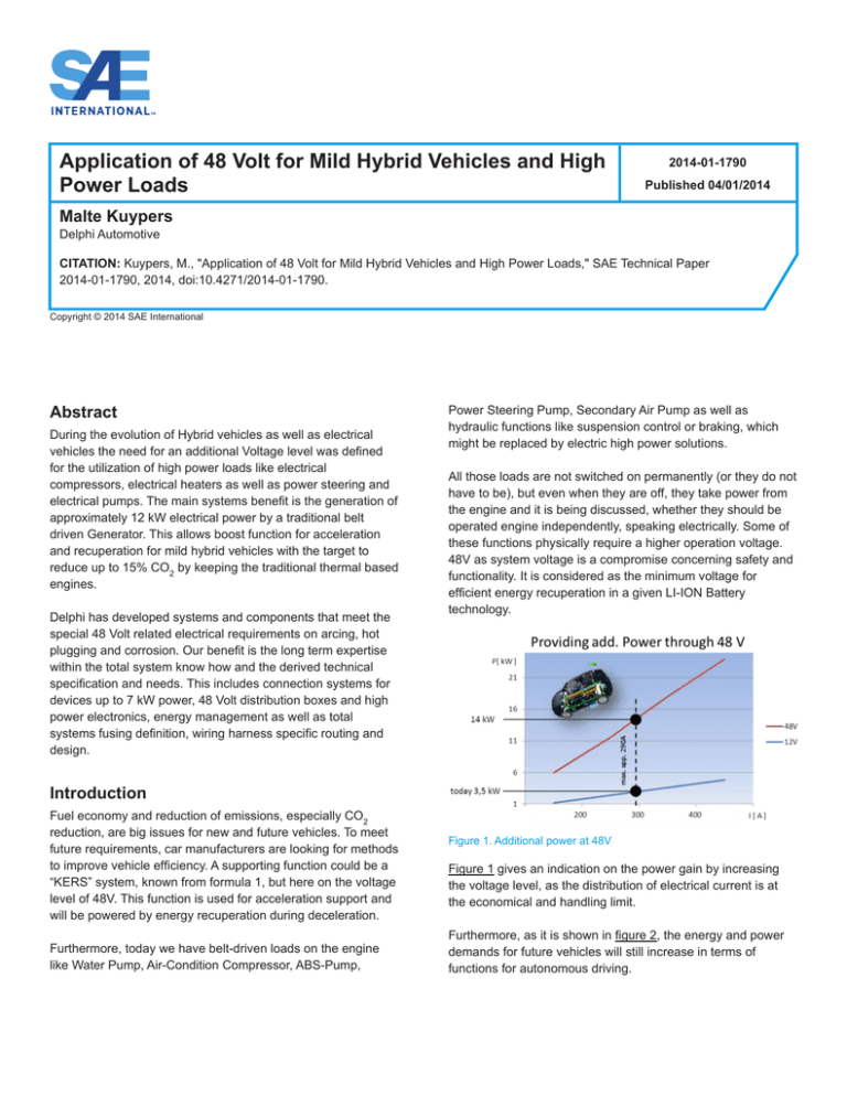
Figure 1. Additional power at 48V
Figure 1 gives an indication on the power gain by increasing
the voltage level, as the distribution of electrical current is at
the economical and handling limit.
Furthermore, as it is shown in figure 2, the energy and power
demands for future vehicles will still increase in terms of
functions for autonomous driving.
Electrical propulsion in Hybrid Vehicles operates on a High
Voltage (HV) Level between 150V and 650V. At this voltage
level a high effort for protection against electrical shock is
legally required. For this reason it is planned to supply high
power functions on the 48V level in Hybrid Vehicles as well,
because the installation effort is considered to be lower.
The corresponding E/E Architecture is like the 48V Base
Architecture where the Motor - Generator is shifted to the HV
level and the lower voltage levels are supplied by a DCDC
converter. This converter is currently considered to operate
from HV to 14V.
Figure 2. Evolution of E/E Systems
Currently discussed general E/E Architectures for application of
an additional voltage level of 48V are indicated in figure 3.
Characteristics and Requirements of the
48V E/E System
Currently the only official specifying document for 48V is the
so-called LV 148, issued by German OEMs.
Figure 4. Voltage levels of 48V System according to LV 148 (Source LV
148 / VW 82148-1 Issue 201109)[1]
Figure 3. Multi-voltage Architectures
The base architecture - depending on the focus of the OEM,
CO2 reduction or performance enhancement - comprises the
unchanged 14V E/E System being powered via a DC/DC
converter in the power class of 3 kW, and the portion of the
48V System as requested, for example a Motor - Generator in
the power range of 12 kW for energy generation, acceleration
support and recuperation plus a storage device on 48V, here a
Li-Ion Battery. In some cases the battery can be substituted or
supported by a super-capacitor, depending on the application.
Once 48V are installed in the vehicle, high power functions as
mentioned earlier are about to follow. These additional
functions have power levels of around 500 Watts to 5 kW.
Currently it is not planned to convert the whole E/E System to
48V.
The LV 148 [1] specifies first of all the voltage levels of the 48V
system as seen in figure 4. The usual operation area is
between 36V and 52V. following are areas with functional
restrictions for under voltage and upper voltage. Important
borders are 54V (U48max, high, limited) and 60V (U48 sh protect). 60V
must not be reached, respectively exceeded. The same applies
for 54V. The area between the levels is a safety margin.
Furthermore the LV 148 specifies test procedures for 48V
components in expected use cases.
In addition the LV 148 provides some premises, where
requirements can be derived from, as:
• Electrical shock protection is not required for DC-Voltage <
60V.
(No High Voltage Interlock System (HVIL) is required to
protect humans against electrical shock)
• A single malfunction must not lead to a Short Circuit
between 48V and 12V E/E System.
(Such a short circuit between the voltage levels without
connection to ground might destroy the complete 12V
System due to permanent overvoltage)
• There is a common ground (chassis) potential for 12V and
48V, which is connected by spatially divided wires and
ground terminals.
(Loss of common ground might lead to reverse voltage on
the 12V side and thus destruction of 12V electronics)
• No component may lead to a transition into the overvoltage
level (54V (U48max, high, limited)) i.e. due to Load Dump or
resonance step-up.
(This is a very important statement, as this requires special
measures at inductive loads and limits the effects of arcing)
The statement mentioned first, that no electrical shock
protection is required has led to the opinion, that 48V or any
voltage below 60V could be treated as 12V.
This is correct concerning the system components as such like
wires, because they are validated for voltages up to 60V (LV
112 or ISO 6722).
But there are some effects at higher voltages like 48V which
might require additional system protection measures for
technical reasons.
One critical effect is arcing. If arcing occurs, the surrounding
materials might be set to fire due to the high temperature of the
plasma of around 6000°C.[2],[3]
Failure Modes in the 14V/48V E/E System
valid for both voltage levels, although special care has to be
given to the involved conductor materials and fuse size. At 48V
the short circuit will be accompanied by an electric (parallel)
arc and therefore the current will be reduced [4] in comparison
to the short circuit without arc. In general a melting fuse can be
considered as feasible solution for classical short circuit
protection.
Loss of Common Ground
As mentioned earlier and especially as one of the premises of
LV 148, loss of common ground has to be avoided. The
recommendation here is separation. Separate GND
connections on dual voltage electronics as for instance DCDC
converters and separate wires to separate GND bolts on the
chassis. If this is not feasible, alternatively an electronic GND
supervision should be installed which could switch off the
power to the device when a failure is detected.
Voltage Short Circuit
A short circuit between the voltage levels has to be avoided. As
stated in the LV 148 it must not occur by a single failure. Here
again the recommendation is separation:
• Separate routing of 14V and 48V power lines and low ohmic
sensor lines
• Separate connectors for different voltage levels
• Additional wall in cable channels if separate routing is not
feasible
Alternatively the voltage short circuit can be handled by
• Application of low-tolerance melting fuses on 48V
• Shielded wires for 48V in order to force a short circuit to
GND
• Shielded wires for 48V in order to detect an insulation fault
• Application of (smart) MOSFETs for switching and output
supervision
Broken Wire
Figure 5. Failure modes in the 14V/48V E/E System
In figure 5 the different failure modes in the dual- or multivoltage E/E System are indicated. The high voltage area is
neglected here, as there is no interaction between HV and the
lower levels due to the fact that the HV System is considered
safe by legal requirements.
Short to Ground
This failure mode is what we usually expect when a short
circuit occurs. Due to the high current a melting fuse will open
the circuit and the current flow is interrupted. This is basically
Broken wire is an arc - creating failure and stands as synonym
for any kind of intermittent contact like bad crimp, loose
terminal, loose connector, damaged insulation by abrasion. On
the contrary to the 14V E/E System, electric arcs are not
self-extinguishing at 48V, as the length of the arc for a 2.4 kW
resistive load (50A @ 48V) can be up to 5 mm.
In figure 6 some examples for arc length are given. The arc
length depends on conductor material, power and type of load.
If an inductive load is disconnected, a voltage overshot can be
observed. Fortunately the LV 148 postulates, that no
component is allowed to generate a voltage entering the
overvoltage area of 54V (U48max, high, limited), meaning that
appropriate measures have to be taken inside the inductive
load. If the disconnection or interruption is caused by a broken
wire, the arc will extinguish when its maximum length is
reached by material destruction.
This may be the really critical scenario because it occurs
unintended on the contrary to opening a connector.
• A: E < 5J small damage
• B: E < 20J material starts melting
• C: E < 200J melting drops at edges
For a given load, the energy can be influenced by the speed of
disconnection. With manual opening of a connector the speed
is difficult to predict. At Delphi some measurements with
different loads and speed were conducted. We used the
DUCON 9.5 terminal system, as it fits nicely to the load
requirements of up to 5 kW in the 48V system. The results are
shown in figures 9 and 10.
Figure 6. Quasi Static Arc Curve
The Ayrton-Equation (Herta Marks Ayrton) is used to determine
arc length in relation to voltage and electrode material. The
coefficients are evaluated experimentally:
Figure 9. hot disconnect @20A and 10 mm/s disconnection speed
Figure 7. Coefficients of Ayrton-Equation
The severity of electric arcs is high, the occurrence is not very
much investigated.
At 20A, 10 mm/s disconnection speed we have an energy of
around 110 Joule. The resulting damage is low, a little
blackening of the terminals, functionality is still given to 100%.
If an intermittent contact occurs in the 14V System for one of
the reasons mentioned above, a function is lost or interrupted.
The wire will be exchanged, the connector plugged correctly
and so on, but the occurrence is not documented well.
If something like that happens at 48V, the vehicle might burn!
The remaining questions are: Is the likelihood of occurrence
high enough to take measures, are cost effective measures
available, are high cost detection systems necessary or can we
just ignore the effect?
The scenario discussed more often is the “Hot Plugging” issue.
When opening a connector with the load being active an arc
will be created. The degree of damage is linked to the arc
energy:
Figure 10. hot disconnect @50A and 10 mm/s disconnection speed
At 50A, 10 mm/s disconnection speed we have an energy of
around 310 Joule. The resulting damage is more spectacular.
The terminals might have to be exchanged.
How to handle that situation, as the power level of around 2400
Watts is supposed to be the most popular in the 48V system.
Functions like PTC Heaters, E-Steering, Active Roll Control,
etc. The LV 148 does not give an answer.
Figure 8. arc energy
Tests have given an indication on the degree of damage
related to the energy and of course to the thermal capacity of
the terminals, respectively the size:
In the past, different concepts for avoiding arcs or minimizing
the effects have led to a variety of connection system
proposals. Currently most of the OEMs are tending to consider
this issue as “misuse”. However, there are different concepts
with different effort available and will be mentioned below.
The more critical effect, since it will occur unintended and
unexpected, is the arcing in a broken wire or unseated terminal
situation.
We simulated this scenario with a relatively small load of 960
Watts and a disconnection speed of 0.5 mm/s. In reality there
would be no disconnection speed at all, besides the gap being
created by melting conductor material, in our case we used
copper with a gauge of 6 mm2.
The result can be seen in figure 11: large flame, melting
conductor.
Figure 13. Corrosion test @ 48V
At 48V (figure 13) the reaction is much more intensive. The
aqueous solution is boiling, material transport is seen by
change of color. This test was stopped after 15 seconds. The
terminals were destroyed due to corrosion.
Recommendations for 48V E/E System
design
General requirements for system layout, system protection,
connection system design are quite rare. Different OEMs are
following different strategies for different applications. Based
on our experience and findings during tests we established a
set of own requirements and derived some recommendations
for the design of a 48V E/E System.
Battery Box
Figure 11. broken wire simulation @ 20A, 0.5 mm/s, conductor material
copper
An additional issue at higher voltages is the effect of intensified
terminal corrosion. In the 14V system we distinguish between
wet and dry areas. Sealed boxes and connection systems are
mandatory for wet areas as for instance engine compartment
and outer area of doors. In dry areas unsealed systems can be
applied.
How about the 48V system? Is it the same situation? We
conducted a test where we applied salt water (5% NaCl) in the
male part of a 2-way 9.5 DUCON connection system and
connected the two terminals to 12V and GND, respectively 48V
and GND. The result can be seen in figures 12 and 13.
In the 12V System the battery is usually a stand- alone
component with accessible permanently powered contacts.
This should be avoided for the 48V Battery.
Due to the higher risk of arcing, the output to the environment
should be switched and protected. The protection should
comprise:
• Electronic battery disconnection switch for output control in
different vehicle modes (production, transport, park, service,
driving)
• Pyrotechnical device for crash protection
• Master Fuse for overcurrent protection related to FET
parameters
Power Distribution Boxes
Components for Power Distribution Boxes (PDBs) as we know
them from the 12V E/E System like fuses and relays are
available for the 48V System from different suppliers.
Figure 12. Corrosion test @ 12V
At 12V (figure 12) some gassing can be observed, but after the
test duration of 60 seconds the terminals show slight change in
color only. The functionality is still given.
Fuses had been developed for the 42V System and the
components can be applied in the 48V System as well, as the
border - requirements are the same. This is valid for relays as
well.
The arising question is:
Will the functionality, as we know it from today's PDBs be
sufficient for the 48V System ?
Based on the requirements we know today, the answer is YES!
BUT this is likely to change, because features like
• Power Shut - Off in certain vehicle modes
• Arc detection
• Current supervision for optimized wiring
might require the application of different technologies.
Pre-Fuse Boxes
Right now there seems to be a trend that the Pre-Fuse-Box will
be an integral part of the 48V - Battery - DCDC Converter System.
This “Box” will provide a switchable and protected 48V Supply
to the vehicle (see DCDC converter section).
Figure 13. Delphi “Energy Storage System” Bi-Directional DCDC
Converter with battery pack included featuring Pre-Fuse functionality
Even if the pre-fuses are not part of that system, at least the
switch will be inside the “Box”, supported by a crash protection
device.
Wires for 48V Application
In this case the pre-fuses could be conventional MEGA(BF2) or MIDI(BF1) - like fuses for 48V.
Some effects like arcing at 48V require special care on wire
type selection.
Bussed Electrical Centers
Aluminum wires are not recommended. If applied, special care
has to be taken for short circuit protection (electronic
supervision) and for vibration resistance.
So far we haven't seen a requirement for arc detection. For
wire protection functionality, conventional melting fuses could
be applied, although every short circuit will be accompanied by
an electric arc. For that reason some OEMs are tending to go
for electronic protection instead of using melting fuses. Some
characteristics of conventional BECs in relation to 48V:
• Available technology for fuses
• Available technology for relays
• 12V and 48V close together at relays (Coil 12V, Contact
48V) common connector should be avoided due to
separation requirements for inter-voltage-short circuit
protection
Automotive wires are specified for a voltage range up to 60V
and therefore can be used in the 48V environment.
Shielded wires like in HV Systems are not considered, if not
required for EMC reasons.
Routing
Routing will be defined according to RQA (routing quality
assessment) plus application of a separation strategy. Special
consideration of routing passes and material selection for
moving parts (doors, axles …), engine-compartment and
underbody routing (environment).
• Hard wired boxes not preferred
Materials
• Durability of relays unclear
Choice of wire types according to same procedures as for 12V
systems. Special focus on flexibility for moving parts and areas
of high vibration impact to reduce the risk of broken wires,
especially with application of Aluminum wires.
• No arc detection
Electric / Electronic Centers (Smart E/E centers)
The future for power distribution boxes will be smart E/E
centers. Here we can implement features like current
supervision, input/output comparison (arc detection).It is
possible to allow over-currents (inrush) for a defined time in
order to design the wiring according to average current.
Electronic Modules (DCDC converters)
Currently there are Converters with a power-range of 3 kW in
discussion. For certain applications unidirectional converters
are sufficient, especially from HV to 12V or from 12V to 48V, if
only a single function has to be supplied, but in most cases a
bi-directional converter will be required.
Color Coding
There is no standard color defined for 48V wiring and
components like in High Voltage Systems where all
components are marked orange. There was an approach by
General Motors to apply light blue color for wires on a 36V
(42V) level to distinguish those wires from the 12V level wiring
related to the higher risk of arcing.
Connection Systems for 48V Application
In general all the connection systems applied in the 12V E/E
System can be used for the 48V System in terms of terminal
distance or creeping distance.
Related to the affinity to arcing and increased sensitivity to
corrosion, precaution should be considered to avoid terminal
destruction. Taking the results of the salt water test (figure 13)
into account, our recommendation here is to apply sealed
connection systems for every 48V application with different
potentials in one connector; for single cavity connectors it may
not be necessary.
single cavity sealing and terminal position assurance to avoid
unseated terminals. The connector can be closed only, if every
part is seated correctly. Thus the chance for arcing is low.
In wet areas we recommend to use single cavity sealing to
assure a long lasting functionality.
Currently discussed functions on the 48V level are on a power
level of 500 Watts to 5 kWatts with a majority of functions
around 2 kWatts. The corresponding current is around 11A to
110A.
The Delphi portfolio offers a wide range of available connection
systems for this area of application.
Selection of a suitable system follows an evaluation procedure
as shown in figure 14, examples of available terminals are
shown in figure 15.
Figure 16. Sealed connection system with DUCON 9.5 female terminal
for wire gauge up to 16 mm2 and continuous current up to 80A.
When it comes to high current connections, for instance
connections to the Motor - Generator and the 48V storage
system, there is always the discussion whether to use bolt-type
connection or pluggable components. The related current level
is about 220A for some seconds and about 60A continuous
current. At this level pluggable devices are available at Delphi,
both solutions are feasible.
An internal evaluation of plug vs. bolt resulted in an advantage
for plugs. Major advantages of the plug solution are linked to
the assembly process:
• Assembly time
• Space requirement for assembly
• No tools needed for assembly
It depends on OEM philosophy which solution will be preferred.
Examples are shown in figure 17.
Figure 14. Evaluation procedure for selection of connection system
Figure 17. Example for high current connection methods
Avoidance of “Hot Plugging”
Although currently there is no defined requirement how to
handle the “Hot Plugging” issue, there are concepts available:
Figure 15. Examples of available terminals for 48V application
A typical connection system for 48V application with a power
demand of up to 4 kW is the DUCON 9.5 system shown in
figure 16. It fulfills the requirements for wet area application as
Component Level
• Place connector at places difficult to access
• Tagging of connector
• Establish repair guideline
• Active barrier for plug and unplug
• Contact geometry
• Defined disconnection speed
System Level
• Automatic disconnection with sensor contact inside the
connector
◦◦ Separate routing of wiring branches or application of
shielded wires
◦◦ Separate connectors for different voltage levels
◦◦ Electronic fusing
• Separate grounding bolts and wires
• Use of sealed connection systems
• Accurate installation and material selection in order to avoid
arc faults
• Manual disconnection with bridge contact
• Arc detection
References
1. NDE_VW82148-1_LV148.pdf LV 148 here: internal VW
standard
2. Kuhn, Paul K., Furse, Cynthia, Smith, Paul “Locating
Hidden Hazards in Electrical Wiring” University of Utah
LiveWire Test Labs Inc. Aged Electrical Systems Research
Application Symposium, October 18-19, 2006 Chicago,
Illinois
3. Hastings, J., Zuercher, J., and Hetzmannseder, E.,
“Electrical Arcing and Material Ignition Levels,” SAE
Technical Paper 2004-01-1565, 2004, doi:10.4271/200401-1565.
Figure 18. Examples for “Hot Plugging” prevention on system level
The last example in figure 18, arc detection, can be used for
detection of a serial arc caused by a broken wire as well.
Comparison of output voltage at the power distribution device
and input voltage at the function control module will deliver an
indication about a fault-free system. A necessary requirement
are detailed data of the function behavior.
Summary/Conclusions
4. Naidu, M., Schoepf, T., and Gopalakrishnan, S., “Arc
Fault Detection Schemes for an Automotive 42 V Wire
Harness,” SAE Technical Paper 2005-01-1742, 2005,
doi:10.4271/2005-01-1742.
Contact Information
Malte.Kuypers@delphi.com
Acknowledgments
Preparation of this paper was supported by Delphi 48V Team:
Dominik Hermes, Stephan Terbeek, Frank Trommer, Andreas
Urbaniak, Christoph Wevelsiep.
Respecting some boundary conditions, the introduction of an
additional voltage level of 48V in the vehicle E/E System is
technically feasible.
The boundary conditions are:
• 48V must not be permanently active
• Application of a Main Disconnection Switch inside the
battery pack featuring vehicle modes crash, park, transport
and service
• Avoidance of inter-voltage short circuit leading to 12V
system loss by
The Engineering Meetings Board has approved this paper for publication. It has successfully completed SAE’s peer review process under the supervision of the session
organizer. The process requires a minimum of three (3) reviews by industry experts.
All rights reserved. No part of this publication may be reproduced, stored in a retrieval system, or transmitted, in any form or by any means, electronic, mechanical,
photocopying, recording, or otherwise, without the prior written permission of SAE International.
Positions and opinions advanced in this paper are those of the author(s) and not necessarily those of SAE International. The author is solely responsible for the content of the
paper.
ISSN 0148-7191
http://papers.sae.org/2014-01-1790


