Negative Photoresist Kit (AL-217) - Sigma
advertisement
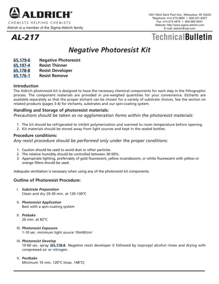
Aldrich is a member of the Sigma-Aldrich family 1001 West Saint Paul Ave., Milwaukee, WI 53233 Telephone: 414-273-3850 • 800-231-8327 Fax: 414-273-4979 • 800-962-9591 Website: http://www.sigma-aldrich.com E-mail: aldrich@sial.com TechnicalBulletin AL-217 Negative Photoresist Kit 65,179-6 65,197-4 65,178-8 65,176-1 Negative Photoresist Resist Thinner Resist Developer Resist Remove Introduction The Aldrich photoresist kit is designed to have the necessary chemical components for each step in the lithographic process. The component materials are provided in pre-weighed quantities for your convenience. Etchants are available separately so that the proper etchant can be chosen for a variety of substrate choices. See the section on related products (pages 3-4) for etchants, substrates and our spin-coating system. Handling and Storage of photoresist materials: Precautions should be taken so no agglomeration forms within the photoresist materials: 1. The kit should be refrigerated to inhibit polymerization and warmed to room temperature before opening. 2. Kit materials should be stored away from light sources and kept in the sealed bottles. Procedure conditions: Any resist procedure should be performed only under the proper conditions: 1. Caution should be used to avoid dust or other particles. 2. The relative humidity should be controlled between 30-50%. 3. Appropriate lighting, preferrably of gold fluorescent, yellow incandescent, or white fluorescent with yellow or orange filters should be used. Adequate ventilation is necessary when using any of the photoresist kit components. Outline of Photoresist Procedure: I. Substrate Preparation Clean and dry 20-30 min. at 120-130°C II. Photoresist Application Best with a spin-coating system II. Prebake 20 min. at 82°C III. Photoresist Exposure 1-10 sec. minimum light source 10mW/cm2 IV. Photoresist Develop 10-60 sec. spray (65,178-8 Negative resist developer I) followed by isopropyl alcohol rinses and drying with compressed air or nitrogen. V. Postbake Minimum 10 min. 120°C (max. 148°C) AL-211 Negative AL-217 AtmosBag™ Photoresist - Inflatable Kit Polyethylene Isolation Chambers DETAILED PROCEDURE I. Substrate Preparation: It is very important that the substrate is free of all organic residues and surface particles removed. Cleaning is accomplished by a thorough solvent rinse followed by baking at temperatures between 120-200°C for up to 20 minutes. Recommended solvent is trichloroethylene. II. Application: A spin-coating system is recommended for achieving a highly uniform and reproducible coating thickness. The substrate should be coated with the photoresist prior to spinning. Never apply the resist while spinning as an uneven distribution may result. Square or rectangular substrates are best coated at low rpm (50-1000 rpm). Undiluted resist at 75 rpm yields about 2.5 µm coatings, the substrate edges and corners being thicker. Resist thickness is dependent on the spin rate and acceleration and the viscosity of the resist. Circular substrates are best coated at a high rpm (2,000-5,000 rpm). Spinning of the substrate at >5,000 rpm has little effect on the thickness of the resist. As viscosity decreases the dependence of thickness on spin rate also decreases. In order to achieve a more uniform and thinner film, and to avoid thickening at the substrate edge, acceleration to peak rpm of 0.1 sec is optimum. Film thickness varies from 0.3 to 2 µm using a spin-coat system. Thick films (1-2 µm) are generally preferred in order to avoid etch penetration and the formation of pinholes. Thick films, however, can result in a loss of resolution. For better results, two thin coats can be applied. III. Prebake: In order to achieve the maximum adhesion of the resist to the substrate, all the residual solvent and volatile components should be removed by evaporation. Failure to thoroughly bake the resist can inhibit the crosslinking necessary for the resist process. Caution should be taken to avoid excessive baking that can result in fogging or decomposition of the resist. Recommended bake-time is 20 min @ 82 °C Baking above 104 °C will adversely affect adhesion. IV. Photoresist Exposure: Any light source with near-UV emissions can be used to expose the photoresist. Large-area light sources should be used only for coarse lines (50 µm or larger). A less diffused light source is necessary for fine line patterns. Recommended fine-line pattern sources are carbon, high-pressure mercury vapor or xenon flash lamps. Proper exposure requires light intensities of ca. 100 mW/cm2. Thickness and processing variable can affect exposure. Exposure times of 1-10 seconds are typically sufficient, providing the light source yields a minimum irradiation of 10 mW/cm2 at the substrate surface. Exposure energy should not vary by more than 10% of optimum value or fine-line definition and reproducibility can be lost. Diffraction effects of the photoresist can cause cross-linking under the mask resulting in line broadening by as much as 2.5 µm. V. Photoresist Development: Spray the developer on to the coated substrate for 10-60 seconds followed by a rinsing several times with isopropyl alcohol. The surface should then be dried by blowing nitrogen or pure, compressed air over it. VII. Postbake: A postbake of the photoresist is required to remove residual solvents and volatile components and helps enhance the chemical stability and adhesion of the resist. The recommended postbake is 10-20 min. at 120 °C and should never exceed 148 °C. 2 AL-211 Negative AL-217 AtmosBag™ Photoresist - Inflatable Kit Polyethylene Isolation Chambers DETAILED PROCEDURE (CONT) VII. Photoresist Removal: Hot chlorinated hydrocarbons, such as those in 65,176-1 Negative resist remover I, swell the photoresist which, in conjunction with hot H2SO4 effectively remove the resist film. Ideal temperature for the remover and H2SO4 is 50-60 °C. Related Products: Etchants Cat. No. Etchant Type 65,181-8 65,184-2 65,182-6 65,183-4 Gold etchant, standard Gold etchant, nickel compatible Chromium etchant, standard Nichrome etchant, standard Compound Semiconductors (0.5 mm thick, single side polished) Cat. No. Composition Diameter (in.) Formula Orientation 65,147-8 65,148-6 65,149-4 Gallium antiminide Gallium arsenide Gallium phosphide 2 2 2 GaSb GaAs GaP (100) (100) (111) Silicon Wafers (0.5 mm thick, single side polished) Cat. No. Orientation Diameter (in.) Semiconductor Type Dopant Resensitivity (Ω cm) 64,668-7 64,710-1 64,753-5 64,754-3 64,767-5 64,770-5 64,776-4 64,777-2 64,778-0 64,779-9 64,780-2 64,781-0 (100) (111) (100) (111) (100) (111) (100) (111) (100) (111) (100) (111) 2 2 3 3 2 2 3 3 2 2 3 3 p-type p-type p-type p-type n-type n-type n-type n-type none none none none boron boron boron boron phosphorous phosphorous phosphorous phosphorous 102-104 102-104 102-104 102-104 10-3-40 10-3-40 10-3-40 10-3-40 10-3-40 10-3-40 10-3-40 10-3-40 3 AL-217 Spin-Coating System SPIN-COATING SYSTEM These compatible, easy-to-use devices provide a convenient step-bystep method for processing metalorganic polymer solutions. The dispenser releases accurately measured amounts onto the spin-coater. The hot plate and UV curer are then used to bake or cure your thin film or coating. This simple system can be used to deposit metal oxide thin films, polymer coatings, and metal organic thin films. Precision Spin-Coater Dispenser, Spin-Coater, Hot Plate, and UV Curer shown above. A two-stage spin process allows dispensing at low speeds and homogenizing the coating at high speeds. Dim.: 8 FW x 8 FH x 10in.D. CE compliant. Specifications: • Vacuum: >2.1CFM • Speed stability: <1% • Stage 1: 500-2,500rpm 2-18 seconds • Stage 2: 1,000-8,000rpm 3-60 seconds Volts Cat. No. 115V 220V Z55,156-2 Z55,158-9 Compact Hot Plate The portable design is convenient to be used in conjunction with the spin-coater. Contains internal thermocouple and has digital control features. CE compliant. Specifications: • Plate dim.: 6 x 6in. • Temp. Resolution: 1°C • Temp. Range: 120–660°F Volts Cat. No. 110V 220V Z55,159-7 Z55,160-0 UV Curer & Dispenser UV Curer: 2 tubes included. Dim.: 8 I x 9 Fin. CE compliant. Specifications: • UV Wavelength: 254nm • Power output: 4 watts/tube • Turn plate: 6rpm Dispenser: Dim.: 8 I x 9 F x 4in. CE compliant. Specifications: • Air: 80–100psi • Air port: Quick-connect Volts Cat. No. Volts Cat. No. 110V 220V Z55,161-9 Z55,162-7 110V 220V Z55,163-5 Z55,164-3 See Technical Bulletin AL-214 for additional parts and information, available at www.sigma-aldrich.com/aldrich. Form AL-217 HJZ 01617-40516 0094 W e a r e c o m m i t t e d t o t h e s u c c e s s o f o u r C u s t o m e r s , E m p l o y e e s a nUV d Curer S h ashown r e h above. olders through leadership in L i f e S c i e n c e , H i g h Te c h n o l o g y and S e r v i c e . © 2004 Sigma-Aldrich Co. Printed in the USA. Aldrich is a member of the Sigma-Aldrich family. Aldrich warrants that its products conform to the information contained in this and other Aldrich publications. Purchaser must determine the suitability of the product for its particular use. See reverse of invoice of packing slip for additional terms and conditions of sale. 4
