Low Voltage HBC Fuselinks - Switch Gears Manufacturers
advertisement
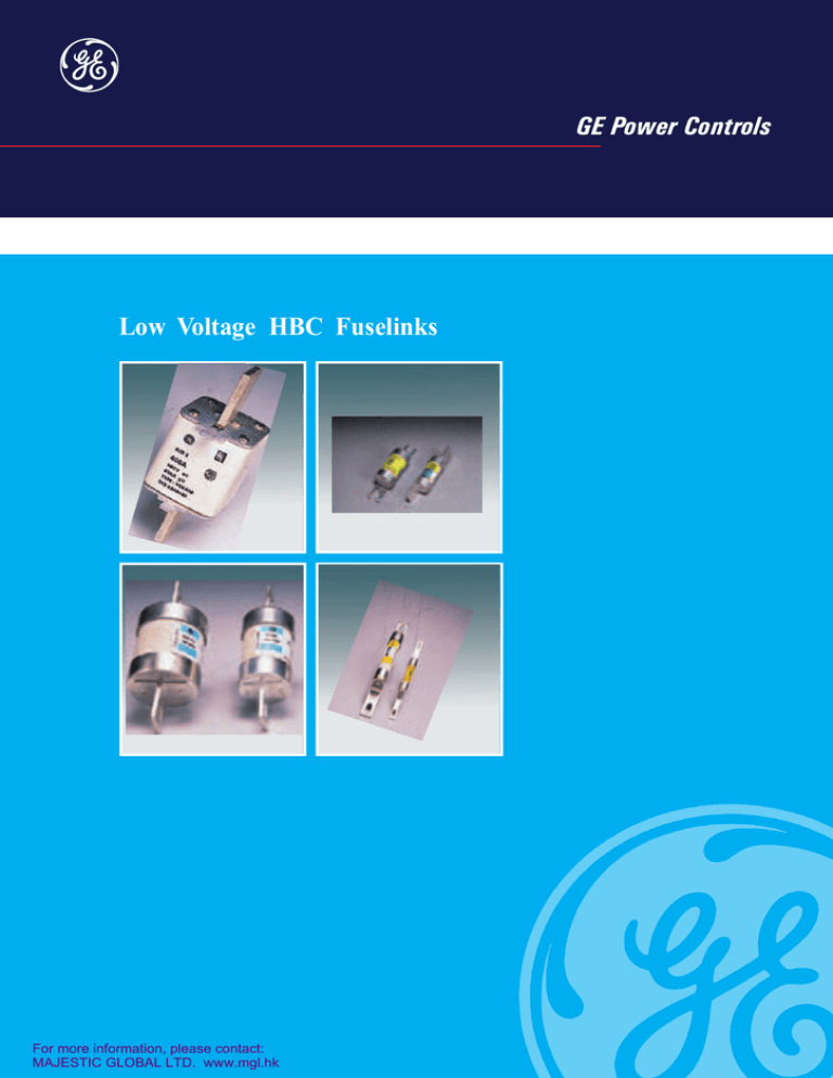
GE Power Controls Low Voltage HBC Fuselinks For more information, please contact: MAJESTIC GLOBAL LTD. www.mgl.hk Low Voltage HBC Fuselinks GE Power Controls type NS/T/TS range of High Breaking Capacity (HBC) fuselinks are extensively used for protection of low voltage circuits. The fuselinks are available in ratings from 2 A to 800 A both in 415V and 660V ac range. All fuselinks comply with the requirements of IS 13703-1993/ IEC 269-1986 and have breaking capacity of 80kA. All fuselinks are ISI certified. The widespread use of GE Power Controls HBC fuselinks are based on the following reasons. High breaking capacity and energy limitation In the event of a damaging short-circuit, the fault energy is severely restricted by rapid fuselink operation. Restriction of electromagnetic stress The fuselinks limit the amount of electromagnetic stress that would otherwise cause severe and costly mechanical damage to current carrying components. Reliability and non-deterioration All fuselinks in practice do not need replacing until one has blown. Proven technology and expertise ensure the highest quality, guaranteeing performance, reliability and years of uninterrupted service. Accurate discrimination In any well designed electrical installation, HBC fuselinks are the main protective device in both primary and branch circuits. The fuselinks will discriminate with each other much more readily than other protective devices. Reliable short-circuit and back up protection The fuselinks are chosen by leading manufacturers of motor starters to provide type 2 co-ordination to IEC 947-4. Low over current protection The current and energy limiting properties of HBC fuselinks ensure that the prospective short circuit currents are restricted to levels well within the overload capability of cables. Class ‘gG’ fuselinks to IS13703/IEC 269 provide close excess current protection enabling cables to be fully rated. Motor circuit capability All fuselinks have time/current characteristics which are suitable for motor circuits. They will withstand motor starting surges without deterioration. Cool running The fuselinks have ‘watts loss’ well within limits specified in International Standards. Approval Approved by the Bureau of Indian Standards and bear ISI marking as a mark of superior quality. 1 Low Voltage HBC Fuselinks 2 Range : Discrimination between Fuselinks Voltage and current as per table below. All have breaking capacity of 80 kA at the respective voltages indicated. Positive discrimination under ‘short-circuit’ conditions is achieved when the larger or ‘major’ fuselink is unaffected by the fault current which caused the smaller or ‘minor’ fuselink to operate. The total operating 2 l t let through by the ‘minor’ fuselink must therefore be less than the pre-arching l2t of the ‘major’ fuselinks. T 660V ac ----TIA TIS TCP -TC TFP TF TKF TM TTM TTM -TLM Type TS 415V ac ----TSA TSS TSD TSD TSDC TSFP TSF TSK TSM TST -TSL TSL Rating (A) Compact range 415V ac SS NS ES EIT --TSDS TSDS ----TSMS TSTS -TSLS TSLS 2, 4, 6, 10, 16, 20 2, 4, 6, 10, 16, 20, 25, 32 2, 4, 6, 10, 16, 20, 25, 32, 36, 50, 63 2, 4, 6, 10, 16, 20, 25, 32, 36, 50, 63 6, 10, 16, 20, 25, 32 36, 50, 63 80,100 125 80, 100 125, 160, 200 125, 160, 200, 250 250, 315 355, 400 450, 500 560, 630 560 630, 670, 710, 750, 800 Main switchboard HBC fuselinks A Outgoing circuits HBC fuselinks B C Outgoing circuits HBC fuselinks Outgoing circuits Fault APPLICATION Steady-load circuits The HBC fuselink selected should have a current rating not less than the normal full-load current of the circuit. Complete Cable Protection Class ‘gG’ ‘T’ range fuselinks provide complete protection and enable cables to be fully rated in accordance with IEE wiring regulations for electrical installation (16th edition). Both overload and short-circuit protection are provided if the current rating of the fuselink is equal to or less than, the current rating of the cable. In some circuits, like motor applications, it is not economical to match fuselink and cable ratings to provide complete cable protection, because of the significant over-currents produced during switching. In such cases, the fuselinks are chosen to provide only short-circuit protection to the associated cables and other circuit components, the necessary over-load protection being provided by other means. Fig. 1 Typical 3 phase (shown single line) distribution system. With properly selected G E Power Controls HBC fuselinks ‘ minor ‘ fuselink ‘C’ operates and ‘ major ‘ fuselinks ‘A’ & ‘ B ‘ remain unaffected Low Voltage HBC Fuselinks Ambient Air Temperatures Capacitor Circuits IS 13703-1993/ IEC 269-1986 on HBC fuselinks requires the fuselinks to be suitable for use in HBC fuselinks are widely used to protect against rupture of the capacitor case and to protect cables and associated equipment from damage in the event of capacitor failure. The fuselink selected must be capable of withstanding a normal full-load current higher than that calculated from the kVA rating (because of circuit hormonics) as well as the high transient current which occurs at ‘switch on’. It has been proved in practice that these requirements are catered for by selecting a fuselink with a current rating not less than 1.5 times the rated capacitor current. These recommendations refer to three-phase power factor correction capacitors. ambient air temperatures not exceeding 400C and recognises that derating may be necessary at higher ambient temperatures. HBC fuselinks in ratings up to 63Amp. can be used at full rating in ambient temperatures up to 600C (in most cases even higher) and ratings 63Amp. to 160Amp. can be used in full rating in ambient temperatures up to 500C. The table 1 gives the derating of fuselinks at higher ambients. These assume that the temperature inside the fuse enclosure is not more than 150C,above ambient air temperature. If the difference between enclosure temperature and ambient temperature exceeds 150C, the enclosure temperature should be used to assess derating. To obtain comparative enclosure temperature add 150C to the figures in Table 1. This table applies only for continuous loads. Where fuse ratings are chosen in motor, capacitor and transformer applications, additional deration is necessary in most cases. Table 1 : Rating Nominal rating (Amp.) 2 4 6 10 16 20 25 32 36 50 63 80 100 125 160 200 250 315 355 400 450 500 560 630 670 710 750 800 450 2 4 6 10 16 20 25 32 36 50 63 80 100 125 160 200 250 300 350 400 425 450 520 570 615 665 710 720 at these Ambient Air Temperature (0C) 50 0 55 0 2 2 4 4 6 6 10 10 16 16 20 20 25 25 32 32 36 36 50 50 63 63 80 75 100 95 125 120 160 145 190 180 235 225 285 270 330 315 380 360 405 380 425 400 495 465 540 510 585 550 630 595 670 630 680 640 60 0 2 4 6 10 16 20 25 32 36 50 63 70 90 110 135 170 210 255 295 340 360 380 440 480 520 560 590 600 65 0 2 4 6 10 16 20 25 32 30 45 55 65 80 105 125 160 200 240 280 320 335 375 410 450 490 525 550 560 3 Low Voltage HBC Fuselinks Selecting GE Power Controls HBC fuselinks for the protection of 3-Phase Induction Motors 4 Warning The recommended rating of GE Power Controls HBC fuselink for a given motor starting duty can be readily obtained by the application of the data set out in Table 2, as illustrated in the example and should be adjusted to suit the starting conditions as indicated below. Motor starting conditions Suitable adjustments to the recommended ratings should be made to allow for the following special conditions which may occur either singly or in combination. Starting currents in excess of the assumed ones. A large no. of starts in rapid succession. The recommendation below allows for 2 starts in rapid succession and upto 8 starts per hour. Ambient temperatures in excess of 400C Long run-up time due to high inertia loads. Any additional information and assistance which may be required regarding the application will be made available on receipt of the relevant details regarding circuit and operating conditions. Example To find the correct fuselink for a 20 H.P. 415 Volt 3 phase induction motor with direct-on-line (DOL) starting: full load current 28 Amp. In Table 2 under the heading ‘Direct-on-line start,’ against the full load current of 28Amp, the fuselink rating is 63 Amp. Table 2 : Recommended ratings of Fuselinks for the protection of 3-Phase Induction Motors D O L Start Star - Delta Start Motor FLC Amp From 0.0 0.8 1.5 2.1 3.1 6.2 9.1 11.1 14.5 15.5 18.1 22.1 28.1 45.1 58.1 80.1 99.1 128.1 180.1 216.1 270.1 328.1 385.1 430.1 500.1 560.1 To 0.7 1.4 2.0 3.0 6.1 9.0 11.0 14.4 15.4 18.0 22.0 28.0 45 58 80 99 128 180 216 270 328 385 430 500 560 620 Recommended fuselink Type ‘gG’ Amp 2 4 6 10 16 20 25 32 36 40 50 63 80 100 125 160 200 250 315 355 400 450 500 560 630 670 Motor FLC Amp From 0 1.5 2.2 3.2 5.6 10.1 14.1 18.1 22.1 28.1 32.1 40.1 51.1 80.1 100.1 125.1 160.1 200.1 250.1 315.1 355.1 400.1 450.1 500.1 560.1 To 1.4 2.1 3.1 5.5 10 14 18 22 28 32 40 51 80 100 125 160 200 250 315 355 400 450 500 560 630 Recommended fuselink Type ‘gG’ Amp 2 4 6 10 16 20 25 32 36 40 50 63 80 100 125 160 200 250 315 355 400 450 500 560 630 Above table is based on the following motor starting performance data Motor Rating Upto 1 kW Direct-on-line starting conditions 5 x FLC for 5 secs Assisted start conditions 2.5 x FLC for 20 secs 1.1 to 7.5 kW 7.6 to 75 kW > 75kW 6 x FLC for 10 secs 7 x FLC for 10 secs 6 x FLC for 15 secs 3.5 x FLC for 20 secs - Do not use wires as replacement for blown HBC fuselinks. Arcing takes place inside HBC fuse cartridge during fault and hence your installation is safe. Bare wire will vapourise and bridge the contacts inside the equipments. This may cause explosion and danger to personnel. - Buy fuselinks only from Authorised Dealers of GE Power Controls India (list available at our offices) to avoid purchase of spurious and rewired fuselinks. - Do not auction blown HBC fuselinks as these are the raw materials for spurious fuselinks. Break the blown HBC fuselinks and sell the caps, tags and elements as scrap. Low Voltage HBC Fuselinks Overall dimensions Staggered tag - SS / NS / ES e 5 a b d - EIT/ TSS h e b k Offset tag a g d b e h k Offset tag - TSA / TIA / TIS / TCP / TSD / TSDS / TFP / TSFP a gg dd Dimensions (in mm) Type a b Ref. SS 24.4 14.1 NS 35.0 14.1 ES 36.0 17.3 EIT(2-32A) 36.3 14.1 EIT(36-63A) 36.3 17.3 TSA 35.0 14.1 TIA 55.0 22.5 TSS 38.8 17.3 TIS 55.0 22.5 TCP 59.0 26.4 TSD 56.0 22.5 TSDS 56.0 22.5 TFP 74.4 40.0 TSFP 57.0 33.7 d e f g h j k 50.0 60.3 66.0 65.5 65.5 83.0 83.9 83.9 83.9 111.0 109.0 89.5 109.8 112.0 11.0 11.0 15.0 11.0 11.0 8.9 8.9 8.9 8.9 19.1 19.0 19.0 19.1 19.0 0.8 0.8 1.2 1.2 1.2 1.2 1.2 1.2 1.2 2.4 2.4 2.4 2.4 2.4 ---55.0 55.0 73.0 73.0 73.0 73.0 94.0 94.0 73.0 94.0 94.0 ---5.5 5.5 5.0 5.2 5.2 5.2 8.8 9.0 6.0 7.1 9.0 -----8.0 8.2 -8.2 11.9 12.0 7.0 10.4 12.0 ---15.0 18.2 15.2 23.5 18.5 23.5 28.0 25.0 25.0 40.7 34.3 Low Voltage HBC Fuselinks Central tag 2 hole fixing b e i h a g d Dimensions (in mm) Type a Ref TC 58.0 TSDC 54.5 TF 75.3 TSF 55.5 TKF 74.0 TSK 55.5 TSMS 57.5 TSTS 58.5 TSLS 62.5 b d e f g h j 26.4 22.5 40.0 33.7 52.6 40.0 52.5 60.0 74.2 133.9 137.0 135.0 131.0 136.0 131.0 162.5 162.5 162.5 19.1 19.0 19.1 19.0 25.4 25.4 25.4 25.4 25.4 3.2 3.2 3.2 3.2 3.2 3.2 5.0 6.3 10.0 111.0 111.0 111.0 111.0 111.0 111.0 133.0 133.0 133.0 8.8 9.0 8.8 9.0 8.8 9.0 11.0 11.0 11.0 11.9 12.0 11.9 12.0 11.9 12.0 16.0 16.0 16.0 i e h 6 a b i i g d Dimensions (in mm) Type a b Ref TM 81.0 60.2 TSM 57.5 52.5 TTM 82.3 74.4 TST 58.5 60.0 TLM 87.5 82.2 TSL 62.5 74.2 d e f g h j k l 208.5 212.5 208.5 212.5 208.5 212.5 25.4 25.4 25.4 25.4 25.4 25.4 5.0 5.0 6.3 6.3 9.8 10.0 133.0 133.0 133.0 133.0 133.0 133.0 11.1 11.0 11.1 11.0 11.1 11.0 15.9 16.0 15.9 16.0 15.9 16.0 ------- 25.4 25.4 25.4 25.4 25.4 25.4 Low Voltage HBC Fuselinks 7 Cubicle mounted switch Independent mounted switch Fuse fittings NSH SM32 SM63 SM125 Safe SC20 SC32 Clip SC63 LP32 LP LP63 WM20 W M WM32 WM63 CH63 CH100 CH CH200 CH315 CHD400 CHD500 CHD CHD630 CHD800 SP1.5 SP SPO2 with SP32-EIT BS SP63-EIT fuses SP32-NS SP63-ES SPO3 SPO5 SPO7 CMM125 CMM200 CMM CMM250 with CMM315 BS fuses CMM400 CMM630 CMM800 • • •• 560A-800A 560A-800A TSLS TSL 450A-500A TSTS TST 355A-400A 355A-400A 450A-500A TSM TSMS 125A-250A 250A-315A TSDS TSK 630A-800A TLM 80A-125A 450A-630A TTM TSF 125A-200A 250A-315A TKF 80A-100A TSDC TF TC 36A-63A TCP • •• • 80A-125A TSS TSD TIS 36A-63A EIT •• 6A-32A 2A-32A EIT •• TSA 2A-63A ES SS •• N S/ SM TIA 2A-20A 25A-32A NS 2A-20A NS CURRENT RATING TS T Type ref. & current PREFIX range LETTERS TYPE NUMBER & CURRENT RANGE Fuselink Selection Chart • • •• • •• • •• ••• • • • •• ••• ••• • •• • • • • • • • • • • • • •• •• • • • •• •• • •• •• • • • Caution : Do not use Fuselinks having current rating higher than the rating of the equipment. Low Voltage HBC Fuselinks Type SS fuselinks Time current characteristics 20000 4hrs 10000 8 TOL : ± 10% on current 1000 Pre-arcing time in seconds 2A 4A 6A 10A 16A 20A 100 10 I2t characteristics 105 1.0 104 0.01 0.005 10 100 r.m.s symmetrical prospective current in amperes 1000 Pre arcing I2t 1 Ampere2 second 103 102 Cut - off characteristics Cut - off current peak kA 100 10 10 20A 16A 10A 6A 4A 1 2A 0.1 0.1 1 10 Prospective current kA (symmetrical r.m.s) 100 1 2 4 6 10 Fuse rating amperes 16 20 I2t at 415 V Total operating 0.1 Low Voltage HBC Fuselinks Type NS / ES / EIT fuselinks 9 20000 4 hrs 10000 Time current characteristics TOL : ± 10% on current 32A 1000 25A Pre-arcing time in seconds 20A 100 16A 10A 10 6A 4A 2A 1.0 0.1 0.01 0.005 1 10 100 1000 r.m.s symmetrical prospective current in amperes Cut - off characteristics Cut - off current peak kA 100 10 32A 25A 20A 16A 10A 6A 1 4A 2A 0.1 0.1 1 10 Prospective current kA (symmetrical r.m.s) 100 Low Voltage HBC Fuselinks Type ES / EIT fuselinks 10 Time current characteristics 20000 4 hrs 10000 Tol : ± 10% on current 1000 36A 50A 63A I2t characteristics 105 Pre - arcing time in seconds 100 2 - 32 A - NS / EIT / ES 36 - 63 A - EIT / ES 10 Total operating I2t at 415 V Pre arcing I2t 104 1.0 0.1 0.01 0.005 10 100 1000 r.m.s symmetrical prospective current in amperes 10000 Aampere 2 second 103 102 Cut - off characteristics 100 Cut - off current peak kA 10 10 63A 50A 36A 1 2 1 0.1 0.1 1 10 Prospective current kA (symmetrical r.m.s) 100 4 6 10 16 20 25 32 Fuse rating - amperes 36 50 63 Low Voltage HBC Fuselinks Type T fuselinks 11 Time current characteristics 20000 4 hrs 10000 Time current characteristics 20000 4 hrs 10000 63 Tol : ± 10% on current 40 36 32 25 100 Pre - arcing time in seconds Pre - arcing time in seconds 1000 20 16 10 10 6 4 1.0 2 0.1 0.01 0.005 800 750 710 670 630 560 500 1000 50 100 10 1.0 0.1 1 0.01 0.005 10 100 1000 r.m.s symmetrical prospective current in amperes 100 1000 10000 r.m.s symmetrical prospective current in amperes 100000 Cut - off characteristics 20000 4 hrs 10000 Cut - off current peak kA 450 400 355 315 250 200 160 125 100 10 100 80 1.0 750 670 560 450 355 250 160 Values given apply at 415 V 550 V values are upto 10% higher. Tol : ± 10% on current 1000 Pre - arcing time in seconds 100 Time current characteristics 660 V values are upto 15% higher 100 63 40 32 20 10 10 1 4 0.1 0.01 0.005 10 100 1000 10000 r.m.s symmetrical prospective current in amperes 100000 0.1 0.1 1 10 Prospective current kA (symmetrical r.m.s) 100 Low Voltage HBC Fuselinks Type T fuselinks 12 Cut - off characteristics 100 800 710 630 500 400 315 200 125 Values given apply at 415 V 550 V values are upto 10 % higher Cut - off current peak kA 660 V values are upto 15% higher 10 80 50 36 25 16 6 1 106 I2t characteristics 2 0.1 105 0.1 1 10 Prospective current kA (symmetrical r.m.s) 100 Total operating I 2t at 660 V at 550 V at 415 V Pre - arcing I2t 106 I2t characteristics Total operating I2t at 660 V at 550 V at 415 V 105 Ampere2 second 104 103 102 Pre arcing I2 t 10 Ampere2 second 104 1 103 200 250 315 355 400 450 500 560 630 670 710 750 800 Fuse rating amperes 102 10 1 2 4 6 10 16 20 25 32 36 40 50 63 80 100 125 160 Fuse rating amperes Low Voltage HBC Fuselinks Type TS fuselinks Time current characteristics 20000 4 hrs 10000 13 Time current characteristics 20000 4 hrs 10000 Tol : ± 10% on current Pre - arcing time in seconds 1000 100 63 10 80 100 Pre - arcing time in seconds 1000 Tol : ± 10% on current 6 10 16 20 25 32 36 50 250 315 450 500 100 10 1.0 1.0 0.1 0.01 0.005 0.1 1 10 100 1000 r.m.s symmetrical prospective current in amperes 0.01 0.005 100 1000 10000 r.m.s symmetrical prospective current in amperes Time current characteristics 20000 4 hrs 10000 Time current characteristics Tol : ± 10% on current 20000 4 hrs 10000 Tol : ± 10% on current 1000 100 10 100 Pre - arcing time in seconds Pre - arcing time in seconds 1000 125 160 200 300 400 1.0 10 0.1 560 630 670 710 750 800 1.0 0.01 0.005 100 1000 100 00 100000 r.m.s symmetrical prospective current in amperes 0.1 0.01 0.005 100 1000 10000 100000 r.m.s symmetrical prospective current in amperes Low Voltage HBC Fuselinks Type TS fuselinks I2t characteristics Cut - off characteristics 14 106 100 80 Cut - off current peak kA 10 63 50 32 25 20 16 Total operating I2t at 415 V Pre - arcing I2t 36 105 10 6 1 4 2 0.1 0.1 Ampere2 second 104 1 10 100 Prospective current kA ( symmetrical r.m.s ) 103 Cut - off characteristics 100 Cut - off current peak kA 500 450 400 355 315 250 200 160 125 102 10 10 1 6 10 16 20 25 32 36 50 63 80 100 125 160 200 250 Fuse rating amperes I2t characteristics 106 0.1 1 10 Prospective current kA ( symmetrical r.m.s ) 100 Total operating I2t at 415 V 105 Cut - off characteristics Cut - off current peak kA 100 800 750 710 670 630 560 10 Pre arcing I2t Ampere2 second 0.1 104 103 1 102 Fuse rating - amperes 0.1 0.1 1 10 Prospective current kA ( symmetrical r.m.s ) 100 10 315 355 400 450 500 560 630 670 710 750 800 Fuse rating amperes Low Voltage HBC Fuselinks GE Power Controls type VS HBC (High Breaking Capacity) fuselinks with blade contacts offer precise and perfect protection to low voltage circuits for industrial and general applications. • 6 amps to 630 amps in five sizes with breaking capacity of 80kA at 500 V ac • Strict compliance to performance and dimensional requirements of Indian and international standards: lS 13703/IEC 269 • Close excess current protection with characteristic type gG • Superior overload performance for motor and capacitor circuits involving surge currents • Very low power loss ensures cool running • Extremely low let through l t and cut off currents at short circuits • Positive indication of fuse operation by flag indicator • Fully tested and certified at CPRI for 500 V ac (at 550V recovery voltage) • lSl certified to lS 13703 - 1993 2 Range : Size 000 00 1 2 3 Type VSA VSB VSF VSK VST Current Rating in Amps 6,10,16,20,25,32,36,50,63 6, 8, 10, 16, 20, 25, 32,36, 50, 63, 80, 100, 125, 160 36, 50, 63, 80, 100, 125,160, 200, 250 250, 315, 355, 400 315, 355, 400, 500, 630 lSG Fusebase List Number ISG 160 ISG 160 ISG 250 ISG 400 ISG 630 * Rated Voltage for lSG Fusebase 660V e3 e3 9.8 b e1 f f b e1 c1 c1 c2 c2 9.8 6 a3 e2 a2 6 a3 a2 e2 a1 Size 000 00 1 2 3 Type VSA VSB VSF VSK VST a1 79.0 79.0 135.0 150.0 150.0 a2 49.0 49.2 66.6 66.6 66.6 a1 a3 44.0 45.2 61.6 61.6 61.6 b 15.3 15.0 23.0 30.0 34.0 c1 35.1 35.0 39.9 48.2 59.7 c2 9.7 9.5 10.0 10.0 9.5 e1 36.0 43.0 51.0 57.0 72.0 e2 21.0 30.0 51.0 56.0 72.0 e3 16.0 20.0 22.0 22.0 22.0 f 6.0 14.0 14.6 13.3 17.8 Dimensional tolerances are as per data sheet in mm 11 of lS 13703/IEC 269 Type ‘lSG’ fuse base is available for VS HBC fuselinks - single pole bases ( 160 A to 630 A ) and three pole base ( 160 A ). 15 Low Voltage HBC Fuselinks Type VSA (Size 000) fuselinks 16 Time current characteristics 20000 4 hrs 10000 Tol ± 10% on current Pre - arcing time in seconds 1000 100 63 50 36 32 25 20 16 10 6 10 I2t characteristics 1.0 Total operating I2t at 500 V Total operating I2t at 415 V Pre arcing I2t 0.1 10 5 0.01 0.005 1 10 100 1000 r.m.s symmetrical prospective current in amperes 10000 Ampere2 second 10 4 10 3 Cut - off characteristics 100 10 2 Cut - off current peak kA Cut - off values are at 500 V ac Cut - off values at 415V are upto 10% lower 10 63 50 36 32 25 20 16 10 6 1 0.1 0.1 1 10 Prospective current kA ( symmetrical r.m.s ) 100 10 6 10 16 20 25 32 36 50 63 Fuse rating amperes Low Voltage HBC Fuselinks Type VSB (Size 00) fuselinks 17 Time current characteristics 20000 4 hrs 10000 Pre - arcing time in second Tol ± 10% on current 1000 160 125 100 80 63 50 36 32 25 20 16 10 8 6 100 10 I2t characteristics Total operating I2t at 500 V Total operating I2t at 415 V Pre arcing I2t 1.0 10 6 0.1 10 100 1000 r.m.s symmetrical prospective current in amperes 10000 10 5 Ampere2 second 0.01 0.005 1 Cut - off characteristics 1000 10 4 Cut - off values are at 500 V ac Cut - off values at 415V are upto 10% lower 10 3 Cut - off current peak kA 100 10 2 160 125 100 80 63 50 36 32 25 20 16 10 10 8 1 0.1 0.1 1 10 Prospective current kA ( symmetrical r.m.s ) 100 6 10 6 8 10 16 20 25 32 36 50 63 80 100 125 160 Fuse rating amperes Low Voltage HBC Fuselinks Type VSF (Size 1) fuselinks 18 Time current characteristics 20000 4 hrs 10000 Pre - arcing time in second Tol ± 10% on current 1000 250 200 160 125 100 80 63 50 36 100 10 I2t characteristics Total operating I2t at 500 V Total operating I2t at 415V Pre arcing I2 t 10 7 1 0.1 10 6 10 100 1000 10000 r.m.s symmetrical prospective current in amperes Ampere2 second 0.01 0.005 Cut - off current characteristics 1000 Cut - off values are at 500 V ac Cut - off values at 415V are upto 10% lower 10 5 10 4 Cut - off current peak kA 100 250 200 160 125 100 80 63 50 36 10 10 3 10 2 1 0.1 0.1 1 10 Prospective current kA ( symmetrical r.m.s ) 100 36 50 63 80 100 125 160 200 250 Fuse rating amperes Low Voltage HBC Fuselinks Type VSK (Size 2) fuselinks 19 Time current characteristics 20000 4 hrs 10000 Tol ± 10% on current Pre - arcing time in second 1000 400 355 315 250 100 I2t characteristics Total operating I2t at 500 V Total operating I2t at 415V Pre arcing I2t 10 107 1 0.1 106 100 1000 10000 100000 r.m.s symmetrical prospective current in amperes Ampere2 second 0.01 0.005 Cut - off current characteristics 105 1000 Cut - off values are at 500 V ac Cut - off values at 415V are upto 10% lower 104 Cut - off current peak kA 100 400 355 315 250 103 10 102 250 1 0.1 0.1 1 10 Prospective current kA ( symmetrical r.m.s ) 100 315 355 Fuse rating amperes 400 Low Voltage HBC Fuselinks Type VST (Size 3) fuselinks 20 Time current characteristics 20,000 4 hrs 10,000 Tol ± 10% on current Pre - arcing time in second 1000 630 500 400 355 315 100 I2t characteristics 10 Total operating I2 t at 500 V Total operating I2 t at 415V Pre arcing I2 t 107 1 0.1 106 0.01 0.005 100 1000 10000 100000 r.m.s symmetrical prospective current in amperes Ampere2 second 106 Cut - off current characteristics 1000 Cut - off values are at 500 V ac Cut - off values at 415V are upto 10% lower 105 100 Cut - off current peak kA 630 500 400 355 315 103 10 102 315 355 400 500 Fuse rating amperes 1 0.1 0.1 1 10 Prospective current kA ( symmetrical r.m.s ) 100 630
