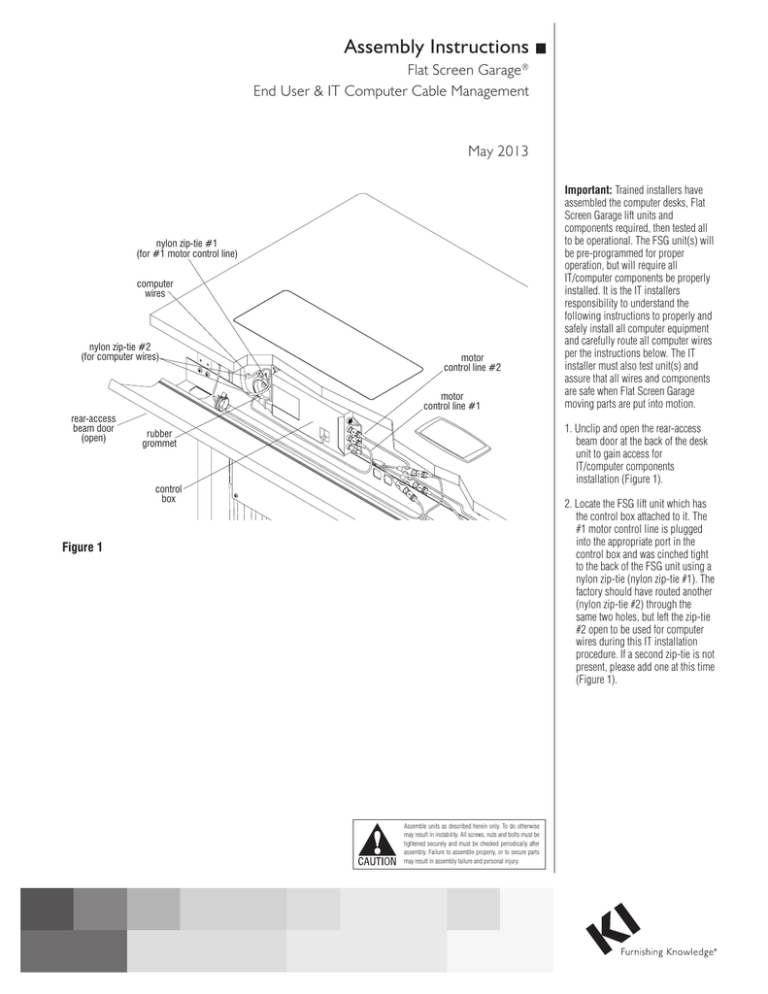
Assembly Instructions Flat Screen Garage® End User & IT Computer Cable Management May 2013 nylon zip-tie #1 (for #1 motor control line) computer wires nylon zip-tie #2 (for computer wires) motor control line #2 motor control line #1 rear-access beam door (open) Important: Trained installers have assembled the computer desks, Flat Screen Garage lift units and components required, then tested all to be operational. The FSG unit(s) will be pre-programmed for proper operation, but will require all IT/computer components be properly installed. It is the IT installers responsibility to understand the following instructions to properly and safely install all computer equipment and carefully route all computer wires per the instructions below. The IT installer must also test unit(s) and assure that all wires and components are safe when Flat Screen Garage moving parts are put into motion. 1. Unclip and open the rear-access beam door at the back of the desk unit to gain access for IT/computer components installation (Figure 1). rubber grommet control box 2. Locate the FSG lift unit which has the control box attached to it. The #1 motor control line is plugged into the appropriate port in the control box and was cinched tight to the back of the FSG unit using a nylon zip-tie (nylon zip-tie #1). The factory should have routed another (nylon zip-tie #2) through the same two holes, but left the zip-tie #2 open to be used for computer wires during this IT installation procedure. If a second zip-tie is not present, please add one at this time (Figure 1). Figure 1 Assemble units as described herein only. To do otherwise may result in instability. All screws, nuts and bolts must be tightened securely and must be checked periodically after assembly. Failure to assemble properly, or to secure parts may result in assembly failure and personal injury. Flat Screen Garage® Troubleshooting/Programming the Control Box Assemble units as described herein only. To do otherwise may result in instability. All screws, nuts and bolts must be tightened securely and must be checked periodically after assembly. Failure to assemble properly, or to secure parts may result in assembly failure and personal injury. 3. Before installation of the flat screen monitor or any computer components, test the powered FSG unit for proper operation. Press and hold the “Up” button at the front, underside of the desk (Figure 2) until the unit’s door opens and the shelf rises and stops at its top position. If this test works properly, skip past “Troubleshooting” to step 4, page 3. Troubleshooting If motor does not cycle as it should, follow the guidelines below and see Figure 2 & Detail A. Check to be sure that the power cord is plugged securely into a power source, and that the other end is plugged securely into the control box with the cord run up through the three strain-relief tabs on the control box side. Also, make sure the appropriate motor control line(s), and Up/Down switch lines are plugged in securely to the proper location on the control box. If the above does not remedy the situation, follow the steps A through D below. A. If the FSG control box installation includes an optional infrared receiver, route the receivers plug up through the 7/8” hole in the center, metal part of the rear-access beam door, then plug the connector into the Red - “IR Receiver” plug of the 3-way splitter (Figure 2 & Detail A). Use the round double sided foam tape to secure the receiver to the underside of the rear-access beam door at this time (Figure 2). Caution: Proper programming of control box is very important. Carefully read warning stickers on control box and front of FSG unit. Carefully read all notes and instructions B through D below. B. The control box must be initialized before the system can be used. First make sure the worksurface is free of anything which might interfere with the movement of the FSG door. Recheck that the power supply is properly connected to the FSG unit(s) and that all control lines are properly positioned in the control box ports. C. To begin programming of units, confirm first that the right-hand Up/Down switch is plugged into 3-way splitter port “MG1”. Then, press and hold the DOWN button for at least five seconds. If there is a second FSG unit on the same table, repeat the above procedure on the second (left-hand) Up/Down switch. The second FSG Note: If any component lines are unplugged from the control box, memory is lost and the initialization process must be repeated to make the unit(s) operate. Also, if power is lost or disconnected during motor operation, the initialization process must be repeated. M3 M2 M1 HS Detail A D. After successful initialization, the individual motors will properly operate up or down using the separate Up/Down button for each unit. Note: If a single motor is cycled for more than four continuous minutes, or two lifts of a dual unit table are cycled for two continuous minutes, duty cycle protection mode is initialized and will rest the motor for 18 minutes. frequency switches infrared receiver Detail B right-hand up/down switch FSG #1 motor control line (to socket M1) rear-access beam door (open) FSG #2 motor control line (to socket M2) 110 volt power cord Note: Frequency choices of either “K1” or “K2” should be set on infrared receiver on each desk. A group of desks or all desks can be set to operate on either of the two channels. If the switch on the receiver (Detail B) is in its left position, channel “K1” is selected, in the middle or right position channel “K2” is selected. 2 unit (plugged into splitter plug “MG2”) must be programmed after the first FSG unit. left-hand up/down switch 3-way splitter (to control box socket HS) FSG #1 Up/Down switch (to “Handset MG1” on splitter) infrared receiver (to “IR-Receiver” on splitter) Figure 2 FSG #2 Up/Down switch (to “Handset MG2” on splitter) Flat Screen Garage® End User & IT Cable Management Assemble units as described herein only. To do otherwise may result in instability. All screws, nuts and bolts must be tightened securely and must be checked periodically after assembly. Failure to assemble properly, or to secure parts may result in assembly failure and personal injury. 4. Begin installation of the flat screen monitor by pressing and holding the “up” button of the Up/Down switch until the unit’s door opens and the shelf rises and stops at its top position (if not tested in step 3). If unit does not lift up as described, go back to page 2 and follow “troubleshooting” procedures after step 3. flat-screen mounting bracket 4mm screws & star washers flat screen monitor Note: A hardware package included with the Flat Screen Garage unit has four 4mm x 16mm and four 4mm x 20mm machine screws and star washers which will fit most applications. Depending on the flat screen monitor manufacturer and model design, installer may have to acquire other appropriate mounting hardware for proper attachment to mounting bracket. Also, many monitor models will have rear covers, or table stand supports that will require removal before installation to FSG unit (consult monitor owner’s manual). Not all monitor styles will install to the unit, and the maximum monitor height above the support shelf must be under 17.25” (Figure 3). 5. Carefully mount the flat screen monitor to the flat-screen mounting bracket in the desired position using appropriate 4mm screws and star washers (Figure 3). Be sure the monitor is mounted low enough (less than 17.25” from top of monitor to surface of shelf support) to allow for proper opening and closing of the FSG top door. It is advised to mount the monitor in the lowest position possible, while still leaving sufficient room below it to store the mouse. Figure 3 6. After monitor installation, remove excess wire(s) from inside the FSG and cycle the FSG unit up and down to make sure the door closes completely and does not contact the monitor. Warning: Excess wire(s) can be damaged when FSG lift cycles up and down. 3 Flat Screen Garage® End User & IT Cable Management Assemble units as described herein only. To do otherwise may result in instability. All screws, nuts and bolts must be tightened securely and must be checked periodically after assembly. Failure to assemble properly, or to secure parts may result in assembly failure and personal injury. 7. Place the keyboard into the Flat Screen Garage as illustrated and ensure there is sufficient clearance between the monitor and keyboard. Lift up keyboard holder and hook onto keyboard as illustrated to secure (Figure 4). remaining slack from the wires inside the FSG unit and pull #2 zip-tie tightly to secure. Run the unit completely up and down a few times to confirm correct length of wires and adjust if necessary. Trim end of zip-tie with wire snips (Figure 5). keyboard holder 8. Store the mouse in the mouse tray directly under the installed flat screen monitor (Figure 4). 9. Using the “down” button under the worksurface front, lower the FSG shelf just enough to view the rubber grommet/opening at the inside rear of the FSG unit. The FSG motor control line will already be run through the grommet and cinched with #1 zip-tie at the backside (Figure 2). Route the monitor power cord through the grommet and plug it into a duplex receptacle on the 10-wire power strip which is mounted to the underside of the worksurface. 10. Next run the monitor’s data wire, the mouse wire and the keyboard line out through the grommet hole for later attachment to the CPU. 11. Use the second nylon zip-tie (installed in factory) just above the grommet hole at the back of the FSG unit (same location as zip-tie #1). To secure the computer wires, place wires in the tie and gently pull slack from the zip-tie. Do not pull tight at this time. Adjust the length of the computer wires by completely lowering the FSG unit. Pull slack out of the wires, making sure they are not wrapped around the bottom of the monitor mounting bracket and push one inch of slack back into the unit. Next raise the unit completely and remove the mouse and keyboard pad from storage and place them in their “use” position. Remove 4 keyboard mouse tray Figure 4 mouse nylon zip-tie #1 (for #1 motor control line) computer wires nylon zip-tie #2 (for computer wires) motor control line rubber grommet Figure 5 Flat Screen Garage® End User & IT Cable Management Assemble units as described herein only. To do otherwise may result in instability. All screws, nuts and bolts must be tightened securely and must be checked periodically after assembly. Failure to assemble properly, or to secure parts may result in assembly failure and personal injury. beam door vertical wireway Detail C 12. Follow the instruction provided with the CPU Sling or CPU Holder (depending on your installation) and set the CPU in place. Note: 60” dual-unit worksurfaces will require the 11” slide tracks. Connect all power and data lines from the CPU to the duplex receptacle under the worksurface and make appropriate data connections to the underside of the PowerUp module (if present). Caution: All wires must be bundled and secured within the beams so that no wires hang down under the worksurface, or outside of the beam. 13. Wires to floor level can be run down the rear of the table leg through a vertical wireway. If already installed to leg, remove the vertical wireway, run wires and re-install it following the step below. vertical wireway D-shaped opening in foot Figure 6 14. Install all remaining vertical wireways to the rear of each leg by first orienting the cut-out section of the wireway down as illustrated. Route the top end of the vertical wireway up and into the D-shaped cut-out in the steel wireway (Detail C), then slide the lower cut-out end of the vertical wireway down into the D-shaped opening in the foot (Figure 6). 5 KI 1330 Bellevue Street P.O. Box 8100 Green Bay, Wisconsin 54308-8100 1-800-424-2432 www.ki.com KI is a registered trademark of Krueger International, Inc. © 2013 KI All Rights Reserved Litho in USA. Code KI-61966R1/KI/GT/0513


