F Pin B F Pin B
advertisement
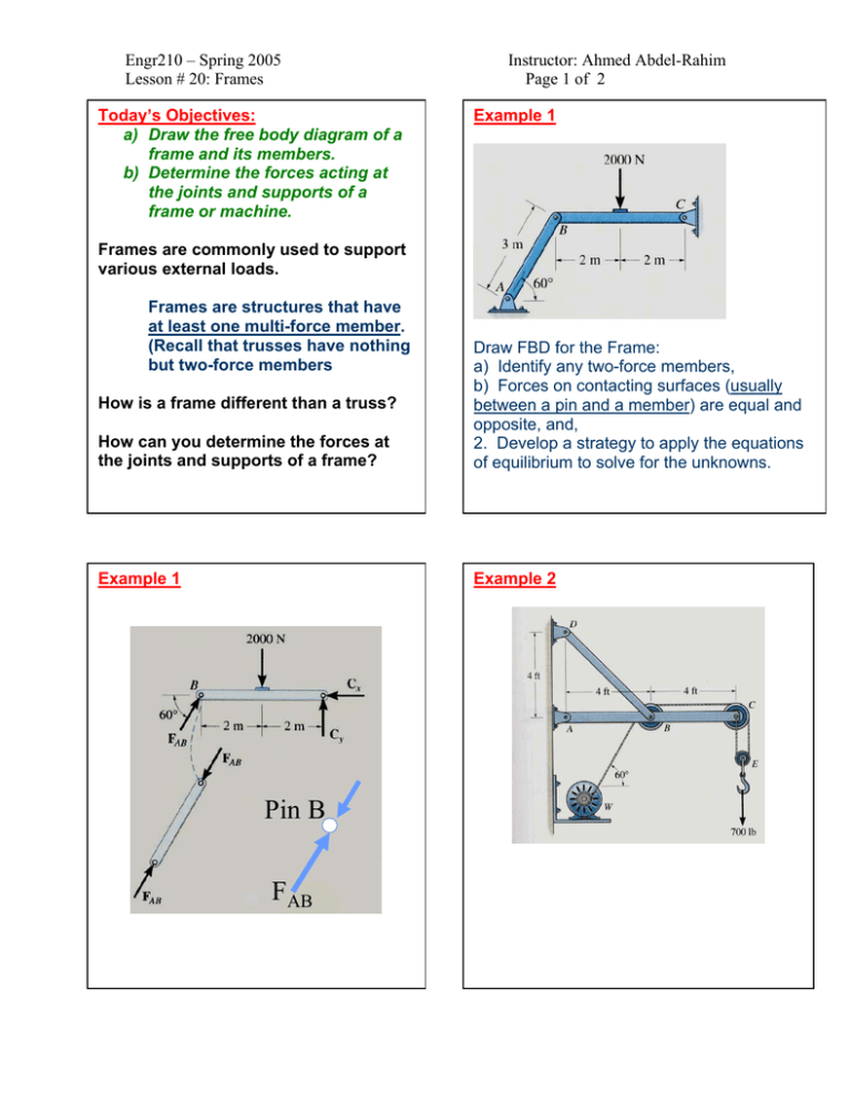
Engr210 – Spring 2005 Lesson # 20: Frames Today’s Objectives: a) Draw the free body diagram of a frame and its members. b) Determine the forces acting at the joints and supports of a frame or machine. Instructor: Ahmed Abdel-Rahim Page 1 of 2 Example 1 Frames are commonly used to support various external loads. Frames are structures that have at least one multi-force member. (Recall that trusses have nothing but two-force members How can you determine the forces at the joints and supports of a frame? Draw FBD for the Frame: a) Identify any two-force members, b) Forces on contacting surfaces (usually between a pin and a member) are equal and opposite, and, 2. Develop a strategy to apply the equations of equilibrium to solve for the unknowns. Example 1 Example 2 How is a frame different than a truss? Pin B FAB Engr210 – Spring 2005 Lesson # 20: Frames Instructor: Ahmed Abdel-Rahim Page 2 of 2 FBD for each Element TBD FBD of the Pulley E 350 lb T T BY BX B 45° 4 ft B 175 lb 303.11 lb 4 ft 350 lb 700 lb A FBD of member ABC 350 lb A FBD of pulley R 700 lb A AY 30° E ∑ MA = TBD sin 45° (4) – 303.1 (4) – 700 (8) = 0 TBD = 2409 lb 350 lb C Y C ∑ FY CX 350 lb ∑ FY = 2 T – 700 = 0, T = 350 lb [E] ∑ FX = CX – 350 = 0, CX = 350 lb [C] ∑ FY = CY – 350 = 0, CY = 350 lb [C] ∑ FX = – BX + 350 – 350 sin 30° = 0 [B] ∑ FY = BY – 350 cos 30° = 0 [B] BY = 303.1 lb BX = 175 lb A FBD of member BD 2409 lb D 45° = AY + 2409 sin 45° – 303.1 – 700 = 0 AY = – 700 lb ∑ FX = AX – 2409 cos 45° + 175 – 350 = 0 AX = 1880 lb A FBD of pulley C + + + + + AX B 2409 lb At D, the X and Y component are + DX = –2409 cos 45° = –1700 lb + DY = 2409 sin 45° = 1700 lb
