Bus Conductors
Bus Conductors
Welding Aluminum Bus to Aluminum Connectors
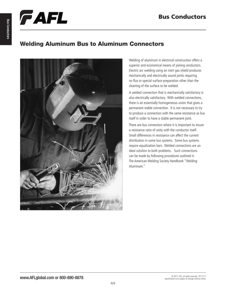
Welding of aluminum in electrical construction offers a
superior and economical means of joining conductors.
Electric arc welding using an inert gas shield produces
mechanically and electrically sound joints requiring
no flux or special surface preparation other than the
cleaning of the surface to be welded.
A welded connection that is mechanically satisfactory is
also electrically satisfactory. With welded connections,
there is an essentially homogeneous union that gives a
permanent stable connection. It is not necessary to try
to produce a connection with the same resistance as bus
itself in order to have a stable permanent joint.
There are bus connectors where it is important to insure
a resistance ratio of unity with the conductor itself.
Small differences in resistance can affect the current
distribution in some bus systems. Some bus systems
require equalization bars. Welded connections are an
ideal solution to both problems. Such connections
can be made by following procedures outlined in
The American Welding Society Handbook “Welding
Aluminum.”
www.AFLglobal.com or 800-890-8878
© 2011, AFL, all rights reserved. 02.15.11
Specifications are subject to change without notice.
628
General Welding Specifications for
Tubular Aluminum Bus Conductor
The following items cover key points that should be included
in specifications for welding aluminum bus conductors. It is
recommended that the references be reviewed in the preparation
of proprietary welding specifications.
4. The working area should be substantially draft free and
should be protected from atmospheric contamination.
5. All connections should be checked before, during and
after the weld is made. Before the weld is begun,
visually inspect the connection to determine proper edge
preparation and alignment. During the weld, maintain
a smooth and continuous flow of metal into the joint
and maintain a constant current setting on the welding
station. When several passes are to be made, check
the previous pass before laying down the next one to
enable detection of poor fusion or cracks. Defective areas
should be removed with a dry chisel prior to application
of subsequent weld passes. After the weld has been
complete, it should be visually inspected again for quality
and to insure the weld bead is of the correct size. The
cross sectional area of the weld should not be less than
that of the smallest member being joined.
1. The welding process and all welding operators should be
qualified in accordance with the Aluminum Association,
“Aluminum Construction Manual” Section 7.2.4
“Qualification of Welding Procedure and Welding.”
2. All Joints to be welded should be free of moisture and
hydrocarbon. Moisture can be removed thermally, but the
temperature applied should not exceed 250oF (121oC). Degreasing should be done with a non-toxic solvent so
as to leave a minimum of residual on the parts. Sufficient
time must be allowed for evaporation of the solvent prior
to welding. Wire brushing with a stainless steel wire brush
should be employed after solvent cleaning to remove
thick heat-treat oxide films, water stains, etc., to permit
optimum fusion and soundness of the weld.
6. Members being joined should be tack welded in place to
prevent misalignment during the welding process.
3. All welds should be made by the gas metal-arc (MIG) or
the gas tungsten-arc (TIG) welding process. Reversed
polarity direct current should be used for MIG welding,
whereas alternating current should be used for TIG
welding. The shielding gas should be welding grade
Argon, Helium, or a mixture of the two. Filler alloy 4043
should be used.
www.AFLglobal.com or 800-890-8878
629
Bus Conductors
Bus Conductors


