MCA Series - Output Transformer Installation
advertisement

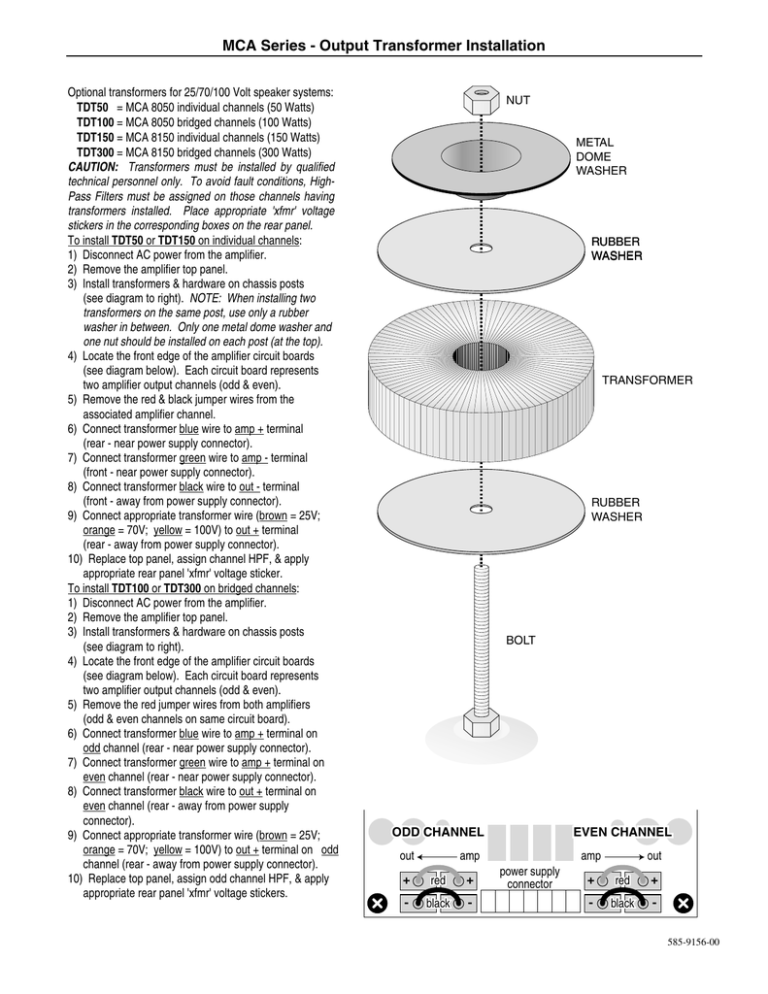
MCA Series - Output Transformer Installation Optional transformers for 25/70/100 Volt speaker systems: TDT50 = MCA 8050 individual channels (50 Watts) TDT100 = MCA 8050 bridged channels (100 Watts) TDT150 = MCA 8150 individual channels (150 Watts) TDT300 = MCA 8150 bridged channels (300 Watts) CAUTION: Transformers must be installed by qualified technical personnel only. To avoid fault conditions, HighPass Filters must be assigned on those channels having transformers installed. Place appropriate 'xfmr' voltage stickers in the corresponding boxes on the rear panel. To install TDT50 or TDT150 on individual channels: 1) Disconnect AC power from the amplifier. 2) Remove the amplifier top panel. 3) Install transformers & hardware on chassis posts (see diagram to right). NOTE: When installing two transformers on the same post, use only a rubber washer in between. Only one metal dome washer and one nut should be installed on each post (at the top). 4) Locate the front edge of the amplifier circuit boards (see diagram below). Each circuit board represents two amplifier output channels (odd & even). 5) Remove the red & black jumper wires from the associated amplifier channel. 6) Connect transformer blue wire to amp + terminal (rear - near power supply connector). 7) Connect transformer green wire to amp - terminal (front - near power supply connector). 8) Connect transformer black wire to out - terminal (front - away from power supply connector). 9) Connect appropriate transformer wire (brown = 25V; orange = 70V; yellow = 100V) to out + terminal (rear - away from power supply connector). 10) Replace top panel, assign channel HPF, & apply appropriate rear panel 'xfmr' voltage sticker. To install TDT100 or TDT300 on bridged channels: 1) Disconnect AC power from the amplifier. 2) Remove the amplifier top panel. 3) Install transformers & hardware on chassis posts (see diagram to right). 4) Locate the front edge of the amplifier circuit boards (see diagram below). Each circuit board represents two amplifier output channels (odd & even). 5) Remove the red jumper wires from both amplifiers (odd & even channels on same circuit board). 6) Connect transformer blue wire to amp + terminal on odd channel (rear - near power supply connector). 7) Connect transformer green wire to amp + terminal on even channel (rear - near power supply connector). 8) Connect transformer black wire to out + terminal on even channel (rear - away from power supply connector). 9) Connect appropriate transformer wire (brown = 25V; orange = 70V; yellow = 100V) to out + terminal on odd channel (rear - away from power supply connector). 10) Replace top panel, assign odd channel HPF, & apply appropriate rear panel 'xfmr' voltage stickers. NUT METAL DOME WASHER RUBBER WASHER TRANSFORMER RUBBER WASHER BOLT ODD CHANNEL out EVEN CHANNEL amp + red + - black - amp power supply connector out + red + - black 585-9156-00

