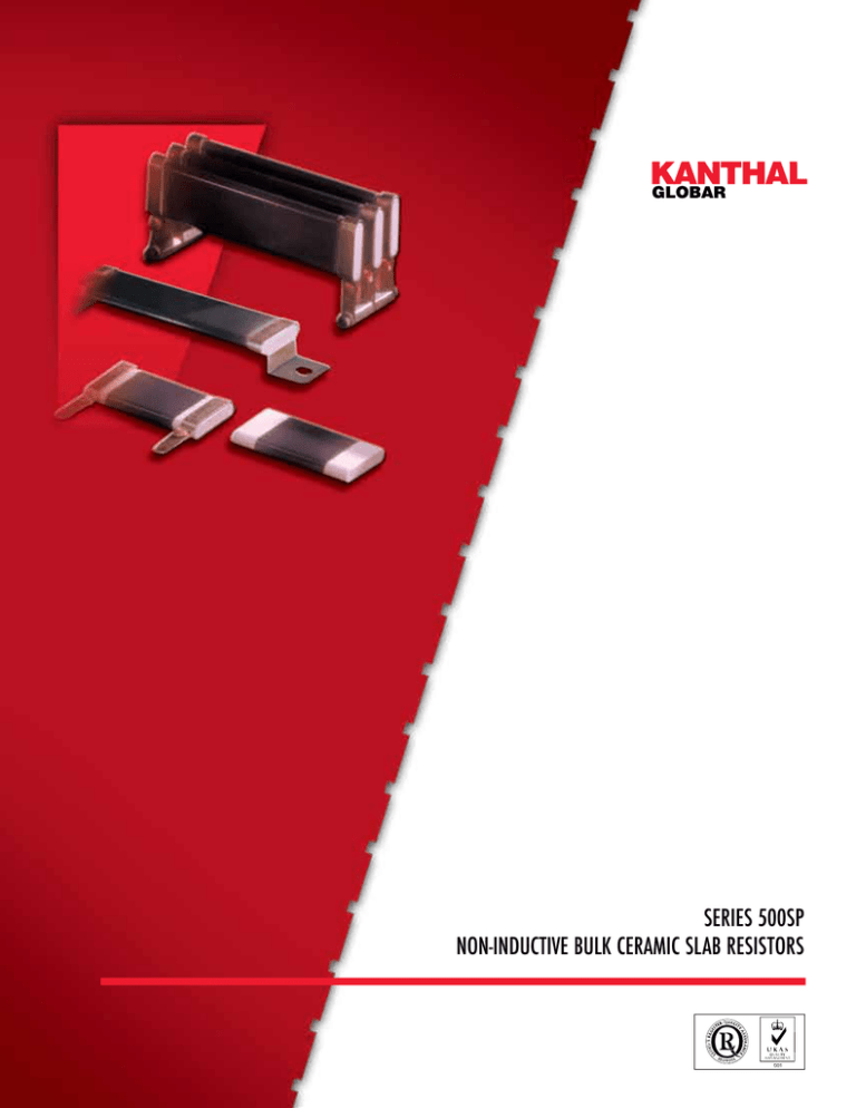
Series 500SP
non-inductive bulk ceramic slab resistors
KANTHAL GLOBAR
Series 500SP Non-Inductive Bulk Ceramic Slab Resistors provide high power and energy dissipation
in a compact size. Proprietary bulk ceramic “SP” material is used in a simple, efficient design that permits
energy to be uniformly absorbed throughout the resistor body, thereby avoiding failure in a peripheral
film or wire.
The advantages of KANTHAL
GLOBAR Bulk Ceramic Slab
Resistors include:
•
Typical Applications:
•
•
•
•
•
•
•
•
Inherently non-inductive, high
reliability due to bulk ceramic
•
•
•
Series 500SP
Non-Inductive Bulk
Ceramic
Slab Resistors
•
•
construction
15 watts per inch of length power
dissipation
Excellent pulse/overload capability
Power Supplies
Power Conditioning Equipment
Soft Start/Current Limit Circuits
Dynamic Braking
Snubber Circuits
RF Dummy Load Circuits
Capacitor Dump Circuits
A cost-effective, space-saving
solution.
Slim profile for excellent volumetric power
efficiency
Resistance range from 0.2Ω to 800Ω
Resistance tolerances 5, 10, 20%
standard on individual components, available
•
•
Motor Drive Controls
to ±2% on assemblies
Rated at 8.5KV for 10" length
Temperature coefficient from +0.2
to -0.08 %/ ° C
The 500SP Series design enables the designer to
minimize resistor package
size and cost while providing unequaled performance and reliability. The slim, compact resistors offer a number of termination options
allowing easy configuration for specific requirements.
SPECIFICATIONS
Resistance Range
Average Power @ Peak* Energy @
Peak Voltage
Type
Length (L) (Ohms)
40°C Amb. (Watts)
40°C Amb. (Joules*)
(Volts)
502SP
2" [50.8mm]
0.2
110
30
150
900
Resistor Weight
(Grams)
15
503SP
3" [76.2mm]
0.3
190
45
290
1900
22.5
504SP
4" [101.6mm]
0.4
280
60
480
2800
30
506SP
6" [152.4mm]
0.8
450
90
800
4700
45
508SP
8" [203.2mm]
1.0
630
120
1100
6700
60
510SP
10" [254.0mm]
1.3
800
150
1400
8500
75
*Based on energy absorption in less than 10 milliseconds. Energy rating can be substantially greater for longer pulses. Contact Kanthal Globar.
•
Standard units are 1" wide by 1/4" thick in variable lengths of 2, 3, 4, 6, 8 and 10 inches.
Other lengths to 10" maximum are available.
•
•
Rated average power is 15 watts per inch of length based on 350°C maximum
operating temperature with 40°C ambient.
Peak impulse current rating is 1000 amps. For applications requiring higher current ratings contact
Kanthal Globar.
STANDARD PRODUCTS
Figure 2. With Straight Radial Tabs (G1)
Figure 1. Without Tabs
Length (L ± 1/16") [L ± 1.6mm]
Length (L ± 1/16") [L ± 1.6mm]
1/4" [6.4mm]
3/8" [9.5mm]
3/8" [9.5mm]
0.030'' [0.8mm]
Typical
1"
[25.4mm]
20 Gage Steel Riveted Tab, Tin-Plated
Hole Spacing (L-3/8'') ± 1/16''
[(L - 9.5mm) ± 1.6mm]
Both Ends Aluminum
Figure 3. With Right Angle Radial Tabs – same direction – (g2)
3/8''
Length (L ± 1/16") [L ± 1.6mm]
[9.5mm]
13/16"
[20.6mm]
0.22" [5.6mm]
Dia. Hole
Figure 4. With Right Angle Radial Tabs – opposite direction – (g3)
Length (L ± 1/16") [L ± 1.6mm]
0.030'' [0.8mm]
Typical
0.030'' [0.8mm] Typical
20 Gage Steel Riveted Tab,
Tin-Plated
20 Gage Steel Riveted Tab,
Tin-Plated
0.22'' [5.6mm]
Dia. Hole
1.5" Max.
[38.1mm]
0.19''
[4.8mm]
1.5" Max.
[38.1mm]
5/16"
[7.9mm]
Typical
(L - 3/8") ± 1/16" [(L - 9.5mm) ± 1.6mm]
1/4'' [6.4mm] Nom.Hole Spacing
0.22'' [5.6mm]
Dia. Hole
(L - 3/8") ± 1/16" [(L - 9.5mm) ± 1.6mm]
1/4'' [6.4mm] Nom.Hole Spacing
0.35''
[8.9mm]
Figure 5. With Low Profile Axial Tabs (h1)
0.19'' 0.35'' 0.19''
[4.8mm] [8.9mm] [4.8mm]
Figure 6. With Standoff Axial Tabs (h2)
Length (L ± 1/16") [L ± 1.6mm]
Length (L ± 1/16") [L ± 1.6mm]
3/8" [9.5mm]
Round Hole
0.275” Dia [7.0mm]
3/4"
[19.1mm]
5/16"
[7.9mm] Typical
3/8" [9.5mm]
Slotted Hole
7/32 x 5/16" [5.6 x 7.9mm]
1/4" [6.4mm]
3/4"
[19.1mm]
1/4"
[6.4mm]
20 Gage Steel, Tin-Plated
Hole Spacing (L + 3/4") ± 1/16'' [(L + 19.1mm) ± 1.6mm]
20 Gage Steel, Tin-Plated
3/4" [19.1mm]
3/4" [19.1mm]
Hole Spacing (L + 7/8") ± 1/16'' [(L + 22.2mm) ± 1.6mm]
5/8" [15.9mm]
3/8" [9.5mm]
5/16" [7.9mm]
Standard Part Numbers
Example Part Number: 504SP101KG1 504SP 101 K G1
Terminal End Options
No Suffix Standard aluminum metalized
ends, no tabs, per Fig. 1
Construction Type
Resistance Value (Ω)
For ≥ 10 Ω: First 2 digits are
significant figures, third digit is
number of zeros to follow, e.g. 101 = 100 Ω
For < 10 Ω An R replaces the
decimal point, e.g. R50 = .50Ω
7R5 = 7.5 Ω
R esistance Tolerance
+
_
J = 5%
+
_
K = 10%
+
_
L = 20%
G1
Straight radial tab, per Fig. 2
G2
Right angle radial tabs, oriented in
same direction, per Fig. 3
G3
Right angle radial tabs, oriented in
opposite direction, per Fig. 4
H1
Low profile axial tabs, per Fig. 5
H2
Elevated axial tabs, per Fig. 6
Tin plated steel radial tabs are standard. Consult factory for other tab materials.
Characteristics
Temperature Coefficient
Short Time Overload:
Max. % change after 5 cycles – 10 times rated power,
5 seconds on, 90 seconds off
-55˚C to +350˚C
100
+ 0.2 to - 0.08 % /˚C
% Of Rated Power
Operating Temperature (1)
+ 2%
Load Life
Max. % change after 1000 hrs. rated power
1-1/2 hours on; 1/ 2 hour off
+ 5%
Thermal Shock
Max. % change after 10 cycles -55˚C to +125˚C
+ 3%
Moisture Resistance
Max. % change when tested per MIL-STD-202, Method 103
+ 5%
Power Rating Curve
120
80
60
40
350˚C
20
0
0
40
80
120
160
200
240
Ambient Temperature ˚C
280
320
360
Resistor Surface Temperature Rise versus Power
340
300
Temperature Rise, degrees C
(1) Note: When required, Type SP material can withstand
short periods of use at red-heat conditions,
i.e. up to 550 to 600°C
Typical Physical Properties:
Density
Specific Heat
Thermal Conductivity
200
100
2.2 - 2.4 gm /cc
0
0.24 - 0.26 cal / gm˚C
0.14 - 0.16 cal/(cm-˚C - sec)
0
20
Individual standard components can be
packaged in series, parallel,
or series/parallel arrays to optimize
energy and power dissipation in available space. Custom assembly packages
are available.
495 Commerce Drive, Suite 7
Amherst, NY 14228-2311
Toll Free: 877-GLOBAR-2 (877-456-2272)
Phone: 716-691-4010
Fax: 716-691-7850
e-mail: sales.globar @ kanthal.com
Internet: www.globar.com
Printed in U.S.A.
60
% of Rated Power
80
100
(Curve is Typical for Resistor Midpoint with Horizontal Orientation in Still Air)
Packaged assemblies
©2013 All Rights Reserved
Form # SP Slab 07/2013
40
120


