6.3:IOM1
Specification Sheet
February 2005
AI and AO Modules (ROC800-Series)
Analog Input (AI) and Analog Output (AO) modules
for the ROC800-Series Remote Operations
Controller provide the ROC with the ability to
monitor and control various analog field values.
The need for fuses has been eliminated on the
Input/Output (I/O) modules through the extensive
use of current-limiting, short-circuit protection, and
surge protection techniques. This results in less
maintenance for remote locations. The I/O modules
are self-resetting after a fault clears.
These modules can be installed in any module slot.
Modules can easily be installed or removed from the
module slots at any time; modules are held in place
by two captive screws. Modules are hot-swappable,
meaning the module can be removed and another
module, of the same kind, can be installed under
power. The modules are hot-pluggable, meaning
they may be installed directly into unused module
slots under power. The modules are also selfidentifying via ROCLINK™ 800 Configuration
Software.
All modules have removable terminal blocks for
convenient wiring and servicing. The terminal
blocks can accommodate a wide range of wire
gauges (12 AWG or smaller).
Each module provides 2500 volts dc of isolation
from other modules and the backplane including
power and signal isolation.
The AI and AO modules provide isolated looppower (+T) sources with integrated short-circuit
protection. This protection limits the amount of
current (+T) during a short-circuit and auto-recovers
after the fault clears.
selectable). For example, one module can provide
+12 volts dc for powering low-power analog
transmitters, while another module in the same
ROC800-Series can provide +24 volts dc for
powering conventional 4-20 mA transmitters.
AI-12
+
–
Out Signal
COM
+
–
–
+
250 Ω
1-5 Volt Device
Externally Powered
1-5 Volt Device
Externally Powered
+ In
ROC809 Powered Device
Current Loop 4-20 mA
AIW1106.dsf
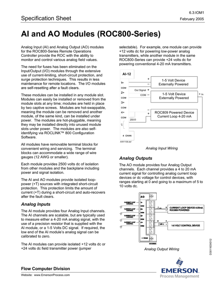
Analog Input Wiring
Analog Outputs
The AO module provides four Analog Output
channels. Each channel provides a 4 to 20 mA
current signal for controlling analog current loop
devices or dc voltage for control devices, with
ranges starting at 0 and going to a maximum of 5 to
10 volts dc.
Analog Inputs
The AI modules can provide isolated +12 volts dc or
+24 volts dc field transmitter power (jumper
Flow Computer Division
Website: www.EmersonProcess.com
Analog Output Wiring
D301163X012
The AI module provides four Analog Input channels.
The AI channels are scalable, but are typically used
to measure either a 4-20 mA analog signal, with the
use of a precision resistor that is supplied with the
AI module, or a 1-5 Volts DC signal. If required, the
low end of the AI module’s analog signal can be
calibrated to zero.
6.3:IOM1
Specification Sheet
Page 2
Analog Input Module Specifications
FIELD WIRING TERMINALS
Terminal
1
2
3
4
5
6
7
8
9
10
Label
1+
COM
2+
COM
3+
COM
4+
COM
+T
+T
Definition
Positive Analog Input
Common Analog Input
Positive Analog Input
Common Analog Input
Positive Analog Input
Common Analog Input
Positive Analog Input
Common Analog Input
Loop Power
Loop Power
INPUT (AI-12 MODULE)
Quantity: 4 channels.
Type: Single-ended, voltage sense. 12-bit
resolution, uses 16-bit A/D converter.
Voltage: 0-5 V dc, 1.22 mV/count.
Impedance: 10 Megohms typical (without scaling
resistor).
Maximum Overload Voltage: ±24V continuous.
Absolute Accuracy1 at 25°C (77°F): ±0.10%.
1
Absolute Accuracy Over Operating Temp:
±0.15%.
Minimum Scan Period: 50 msec for all channels.
POWER CONSUMPTION
Main power supply loading at the Battery Terminals
(at 12.0 volts dc): 84mA typical.
Additional loading that may apply:
+T @ 12V: 1.25 multiplied by Measured
Current Draw at +T Terminal
+T @ 24V: 2.5 multiplied by Measured
Current Draw at +T Terminal
WIRING
12 AWG or smaller at the removable terminal
block.
LOOP POWER
+T Sensor Supply Voltage: Jumper selectable
between 12 V dc and 24 V dc.
+T Sensor Supply Current: 85 mA at nominal 12
or 24 V dc.
ISOLATION
Field to Logic: 2500 V dc, 1 minute minimum.
Field to Power: 2500 V dc, 1 minute minimum.
Module to Module: 2500 V dc, 1 minute minimum.
WEIGHT
56.7 g (2.0 oz).
ENVIRONMENTAL
Same as the ROC800-Series unit in which it is
installed.
DIMENSIONS
26 mm W by 133 mm H by 75 mm D (1.04 in. W by
5.25 in. H by 2.96 in. D).
APPROVALS
Same as the ROC800-Series unit in which it is
installed.
1. Absolute Accuracy Includes: Linearity, Hysteresis, Repeatability, Stability, Gain, and Offset error.
6.3:IOM1
Specification Sheet
Page 3
Analog Output Module Specifications
FIELD WIRING TERMINALS1
Terminal
1
2
3
4
5
6
7
8
9
10
Label
CH 1+
COM
CH 2+
COM
CH 3+
COM
CH 4+
COM
N/A
N/A
Definition
Positive Analog Output
Analog Output Return
Positive Analog Output
Analog Output Return
Positive Analog Output
Analog Output Return
Positive Analog Output
Analog Output Return
Not Used
Not Used
OUTPUT
Quantity: 4 channels.
POWER CONSUMPTION
Main power supply loading at the Battery Terminals (at
12.0 V dc): 100 mA maximum over operating
temperature range.
Additional loading that may apply:
Output @ 12V: 1.25 multiplied by Measured
Current Draw per channel output.
Output @ 24V: 2.5 multiplied by Measured
Current Draw per channel output.
WIRING
12 AWG or smaller at the removable terminal block.
LOOP POWER
Sensor Supply Voltage: Jumper selectable between
12 V dc and 24 V dc.
Sensor Supply Current: 0-20.83 mA per channel.
Type: Single-ended, current control. 16-bit
resolution.
Maximum Input Overload Voltage: ±24 V dc,
continuous.
2
Output Load at 12 Volts DC : 300 ohms
maximum.
Output Load at 24 Volts DC2: 750 ohms
maximum.
Absolute Accuracy3 at 25°C (77°F) with full
load:
Loop Power set for +12 V dc = 0.045%.
Loop Power set for +24 V dc = 0.200%.
Absolute Accuracy3 Over Operating Temp with
full load:
Loop Power set for +12 V dc = 0.25%.
Loop Power set for +24 V dc = 0.35%.
Reset Action: User selectable between outputs
going to software-configured value or to last value
on power-up (on restart).
ISOLATION
Field to Logic: 2500 V dc, 1 minute minimum.
Field to Power: 2500 V dc, 1 minute minimum.
Module to Module: 2500 V dc, 1 minute minimum.
WEIGHT
54.4 g (1.92 oz).
ENVIRONMENTAL
Same as the ROC800-Series unit in which it is
installed.
DIMENSIONS
26 mm W by 133 mm H by 75 mm D (1.04 in. W by
5.25 in. H by 2.96 in. D).
APPROVALS
Same as the ROC800-Series unit in which it is
installed.
Minimum Scan Period: 50 msec on all channels.
1. AO modules W38199 with front labels that read AO-16 are an earlier version that control the low side. AO modules W38269 with front
labels that read AO are the newer version (January 2005 and later) that control the high side.
2. If all channels are at 100% output and R load is < 100 ohms on each channel, then the unit’s operating temperature range must be
reduced by 1 degree/channel when maximum battery voltage is applied to the unit.
3. Absolute Accuracy Includes: Linearity, Hysteresis, Repeatability, Stability, Gain, and Offset error.
6.3:IOM1
Specification Sheet
Page 4
ROCLINK is a mark of one of the Emerson Process Management companies. The Emerson logo is a trademark and service mark of Emerson Electric Co. All other
marks are the property of their respective owners.
The contents of this publication are presented for informational purposes only. While every effort has been made to ensure informational accuracy, they are not
to be construed as warranties or guarantees, express or implied, regarding the products or services described herein or their use or applicability. Fisher Controls
reserves the right to modify or improve the designs or specifications of such products at any time without notice.
Emerson Process Management
Flow Computer Division
Marshalltown, IA 50158 U.S.A.
Houston, TX 77065 U.S.A.
Pickering, North Yorkshire UK Y018 7JA
© Fisher Controls International, LLC. 2002-2005. All Rights Reserved.


