mc 66 Quick Start: The Channel Fader Strip
advertisement

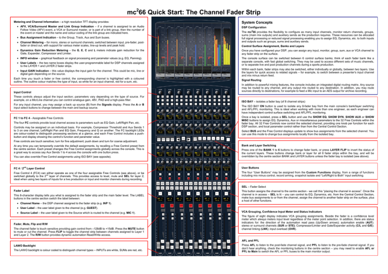
mc266 Quick Start: The Channel Fader Strip Metering and Channel Information – a high resolution TFT display provides: • AFV, VCA/Surround Master and Link Group Indication – if a channel is assigned to an Audio Follow Video (AFV) event, a VCA or Surround master, or is part of a link group, then the number of the event or master and the name and colour coding of the link group are indicated here. • Bus Assignment Indication – to the Group, Track, Aux and Sum buses. • Channel Metering – for mono, stereo or surround channels; switched between input, pre-fader, postfader or direct out, with support for various meter scales, line-up levels and peak hold. System Concepts DSP Configuration The mc266 provides the flexibility to configure as many input channels, monitor return channels, groups, sums (main mix outputs) and auxiliary sends as the production requires. These resources can be allocated full signal processing or reduced signal processing enabling you to assign EQ, Dynamics, etc. to both inputs and outputs such as groups, sums and auxiliary sends. Control Surface Assignment, Banks and Layers • Dynamics Gain Reduction Metering – the G, E, C and L meters indicate gain reduction for the Gate, Expander, Compressor and Limiter. Once you have configured your DSP, you can assign any input, monitor, group, sum, aux or VCA channel to any fader strip on the surface. • INFO window – graphical feedback on signal processing and parameter values (e.g. EQ, Panning). The console surface can be switched between 6 control surface banks; think of each fader bank like a separate console, with fast global switching. They may be used to access different sets of music channels, or to separate live and post production channels during a sports production. • User Labels – the two name boxes display the user-programmable label for DSP channels assigned to the LAYER 1 and LAYER 2 fader strips. • Input GAIN Indication – this value displays the input gain for the channel. This could be mic, line or digital gain depending on the source. Each time you touch a fader or free control, the corresponding channel is highlighted with a coloured outline. The outline colour matches the type of input, so white for an input channel, red for a sum, etc. Input Control These controls always adjust the input section; parameters vary depending on the type of source. For example, on a Mic/Line channel you can control analogue gain, 48V, PAD and a high-pass filter. For any input channel, you may assign a back up source (B) from the Signals display. Press the A or B input select buttons to change between the main and backup source. FC 1 to FC 4 - Assignable Free Controls The four FC controls provide local channel access to parameters such as EQ Gain, Left/Right Pan, etc. Controls may be assigned on an individual basis. For example, Compressor Threshold and Aux Sends 1 to 3 on one channel, Left/Right Pan and EQ Gain, Frequency and Q on another. The FC backlight LEDs are colour-coded to distinguish processing sections at a glance, and each Free Control includes a pushbutton and display showing the control’s function and parameter value. Within each bank, fader strips may also be switched, either individually or globally, between two layers. Use the layers for quick access to related signals – for example, to switch between a presenter’s input channel and mix minus return feed. Signal Routing In addition to powerful mixing features, the console includes an integrated digital routing matrix. Any source may be routed to any channel, and any output mix routed to any destination. In addition, you may route sources directly to destinations, for example to feed a Mic input to an AES output for archive recording. ISO BAY – isolates a fader bay (of 8 channel strips) The ISO BAY ON button is used to isolate any 8-fader bay from the main console’s bank/layer switching and AFL/PFL monitoring. This is ideal when working with more than one engineer, as each engineer can have independent control surface switching and AFL/PFL monitoring. Once a bay is isolated, press a SEL button and use the SHOW EQ, SHOW DYN, SHOW AUX or SHOW MISC buttons to assign EQ, Dynamics, Aux or miscellaneous parameters to the 32 Free Controls within the fader bay. All 32 Free Controls now control the selected channel, providing one knob per function for each DSP section, and local parameter control rather than from the Central Control Section. Select BUS and the Free Control displays update to show bus assignments from the selected channel. You can use this mode to change bus assignments locally from the isolated bay. Free controls are touch sensitive; turn for fine adjustment; push down and turn for coarse adjustment. At any time you can temporarily override the default assignments, by recalling a Free Control preset from the centre section. Each preset changes the Free Control assignments globally across the console. This is a great way to access say Aux Sends 1 to 4 across the console with one button press. Bank and Layer Switching You can also override Free Control assignments using ISO BAY (see opposite). Press one of the BANK 1 to 6 buttons to change fader bank, or press LAYER FLIP to invert the status of the current layers. These buttons change bank or layer for all 8 fader strips within the bay, and will be overridden by the centre section BANK and LAYER buttons unless the fader bay is isolated (see above). FC 4 / 2nd Layer Control User Buttons Free Control 4 (FC4) can either operate as one of the four assignable Free Controls (see above), or be switched globally to the 2nd layer of channels. This provides access to level, mute and SEL for layer 2; ideal when using two layers of inputs for a live production or input and monitor channels during recording. The four “User Buttons” may be assigned from the Custom Functions display, from a range of functions including mix minus control, record arming, snapshot isolate and “Left/Right to Both” input switching. SEL – Fader Select Fader Label This 8-character display tells you what is assigned to the fader strip and the main fader level. The LABEL buttons in the centre section switch the label between: • Channel Name – the DSP channel assigned to the fader strip (e.g. INP 1). This button assigns the channel to the centre section - we call this “placing the channel in access”. Once the channel is in access – SEL is lit – you can control its EQ, Dynamics, etc. from the Central Control Section, make bus assignments to or from the channel, assign the channel to another fader strip on the surface, plus a host of other functions. • User Label – the user label given to the channel (e.g. GUEST). • Source Label – the user label given to the Source which is routed to the channel (e.g. MIC 1). Fader, Mute, Flip and R/W The channel fader is touch sensitive providing gain control from –128dB to +15dB. Press the MUTE button to mute or cut the channel. Press FLIP to toggle the channel strip between channels assigned to Layer 1 and Layer 2. The R/W button provides dynamic automation Read/Write access. VCA Grouping, Confidence Input Meter and Status Indicators The figure of eight display indicates VCA grouping assignments. Beside the fader is a confidence level meter which always meters input level regardless of the meter point selection. In addition, there are status indicators for: the direction of the automation read pass (Up/Down arrows); automation enable (AUT); stereo or surround channels (SUR or STE); Compressor/Limiter and Gate/Expander activity (C/L and G/E); channel linking (LNK); input overload (OVR). AFL and PFL LAWO Backlight The LAWO backlight is colour coded to distinguish channel types – INPUTs are white, SUMs are red, etc. Press AFL to listen to the post-fade channel signal, and PFL to listen to the pre-fade channel signal. If you don’t hear anything, check the monitoring buttons in the centre section – you may need to enable AFL or PFL to Main to switch the AFL or PFL buses to the main monitor output. The Central Control Section – provides master channel control for the channel in access: • INPUT MIXER – input gain, preamp and stereo input controls. • IMAGE – width and positioning for a stereo channel. • DIG AMP (digital gain), DELAY (channel delay), INSERT (insert switching) and DIROUT (channel direct output). mc266 Quick Start: The Centre Section Central Touch-screen Across the top you will see the channel “in access” (INP 1), the time (or timecode) and the current production/snapshot (World Cup 2010/Opening). The remainder of the touch-screen works in conjunction with the SCREEN CONTROL panel (see below) and console keyboard. Here you can select displays for Signal routing, Channel settings, Snapshots, Productions, Metering, etc. • METER – meter point selection (input, pre-fade, etc.) • DYNAMICS – gate, expander, compressor and limiter. • SCF/FILTER/EQUALIZER – 4-band EQ + 2-band Filter + 2band Sidechain Filter. • PAN/HYP-PAN – multi-channel panning including joystick, LFE and Hyper Pan modes (ideal for surround sources). PRODUCTION – the UPDATE PROD button stores settings into the active production; the button flashes as a reminder to save. • FADER – local fader level, mute, AFL and PFL. MONITORING – this touch-screen panel provides monitor source selection, monitoring options, and level, dim and cut for the Control Room 1, Control Room 2 and Studio/PFL monitor outputs. • CHANNEL – monitor channel input switching, snapshot isolate, mix minus control, AFL for individual modules (LISTEN), and automation controls (ABS/TRIM). USER PANELS – space for up to 3 user panels. • AUX SENDS/ AUDIO FOLLOW VIDEO – 32 aux sends and audio follows video event control. Press SHOW to page functions onto the front panel controls. Remember to turn ON the DSP section to hear your changes. Press the SCREEN CONTROL CHAN CONFIG button for visual feedback on your settings. The SEL (Selection) buttons are used for copying or resetting audio parameters, linking modules between channels, or selecting modules for timecode automation or sequence cross fades. SEL ALL will select or deselect all modules. PARAMETER COPY/ASSIGN – used to copy or reset DSP parameters, and to assign parameters to fader strip free controls. Free Control Assignment: first touch the control – for example, touch EQ Band 4 Q; you will see its name appear in the clipboard. Then touch the free control on the destination channel strip. Copy or Reset Audio Parameters: select the fader strip you wish to copy from (press its fader strip SEL); then press COPY, ONE and the SEL button on the EQ module. Now select the destination channel (press its fader strip SEL); the setting is copied. FC PRESETS – Free Control Presets These buttons override the default channel Free Control assignments. For example, press EQ/FIL to assign EQ Band 1 on/off, Gain, Frequency and Q to the Free Controls on every channel. Press the button again to assign EQ Band 2, and so on. Press FC4/2nd to switch Free Control 4 to the second layer. Options include User Buttons, Intercom, Dynamic Automation and Machine Control. Space is also provided in the over bridge for external metering. STRIP ASSIGNMENT and ACCESS CHANNEL/ASSIGN Any type of channel can be assigned to any fader strip using the STRIP ASSIGNMENT and ACCESS CHANNEL/ASSIGN panels. For example, to assign input channel 8 to fader strip 24 – first, press INP and then 008 on the numeric keypad to put INP 8 into access; its name appears in the NAME display. Then press ASSIGN, followed by the fader SEL on the destination fader strip. Several short cuts are available to make multiple fader strip assignments in one operation (FIRST LAST), insert a channel into the existing desk layout (INSERT MOVE), or make assignments to BOTH LAYERS, ALL BANKS, etc. BANK and LAYER Switching Use the ISO buttons to isolate a fader strip from bank switching – press SEL FADER, then select the fader strip to isolate. Press one of the BANK 1 to 6 buttons to switch all fader strips to a new control surface bank. Press LAYER FLIP to invert the layers for all fader strips. Press ALL 1ST or ALL 2ND to switch all fader strips to Layer 1 or Layer 2. Use the MAIN BAY button to apply BANK or LAYER switching only to the 8 main faders. FADER CONTROL, LINK, USER BUTTON and LABEL switching SNAPSHOT/SEQUENCE – for control of Sequence automation. A sequence is a list of snapshots which can be played out in sequence during a live show. The transition between snapshots can be cross faded, and offsets can be applied to deal with last minute changes such as a new artist. BUS ASSIGNMENT – assigns channels to buses: The FADER CONTROL panel allows you to control variable levels from the faders. For example, to control auxiliary send levels, press AUX and then use the left/right arrow buttons to select the aux send. The LINK buttons can be used to link processing sections across multiple channels or create a temporary COUPLE group. Nine USER BUTTONS may be programmed from the Custom Functions display. The LABEL buttons switch the 8-character fader strip label displays FORWARD – routes a single channel to multiple bus outputs. REVERSE – routes a destination (e.g. a sum) from multiple inputs. SCREEN CONTROL – access to the console’s displays. For example, press the SEL button on the fader strip controlling Sum 1. Then press REVERSE FADER, followed by the SEL buttons on the source channels; assigned channels are shown in red; unassigned channels in green. If the bus is configured for stereo or surround, then the corresponding pan law is applied. 10 screen selection buttons provide access to displays such as signal routing (SIGNAL), snapshots (SNAP SEQ), productions (PROD) etc. Some displays feature more than one page, so you may need to press the button again to cycle through to the correct page. 8 Main Fader Strips The 8 main fader strips may control any channel type – input channels, monitor return channels, groups, sums, auxiliary masters, VCAs – in exactly the same way as a channel fader strip. The only differences are that main faders do not have input or free controls. By focusing on different parts of a display you will find that the 4 soft key functions update in order to perform different operations. For example, to route an input to an output from the Signals display - first press SIGNAL. Then select a source on the left and a destination on the right of the display using the trackball. Having made your selections, press the CONNECT soft key to connect the signals. Often there are two pages of soft key functions so press PAGE to access the second level. To enter names, use the console keyboard.


