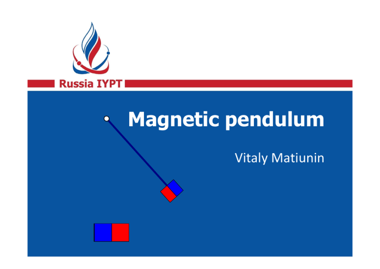
Magnetic pendulum
advertisement

1 Magnetic pendulum Vitaly Matiunin The problem Make a light pendulum with a small magnet at the free end. An adjacent electromagnet connected to an AC power source of a much higher frequency than the natural frequency of the pendulum can lead to undamped oscillations with various amplitudes. Study and explain the phenomenon. 2 3 First observations Experimental setup 4 Rotation sensor Light wooden plank Frequency ≈ 1 Hz Neodymium magnet Electromagnet Undamped oscillations 5 Plan of the report Magnets interactions Conditions for undamped oscillations Experimental detection of undamped oscillations Orders of resonance Cycles of undamped oscillations 6 Main goal of our investigation Prediction of undamped oscillations Computer simulation Theoretical model Poincare map 7 8 Qualitative explanation Region of magnets’ interaction 9 A magnet on the pendulum interacts with the electromagnet only flying over it. The span happens with almost constant velocity. 10° 10° Limitations of amplitudes 10 180 Characteristic times and frequencies v 2 gl 2.5 m/s 2d 0.04 s v 1 f 25 Hz 10 DC solenoid 11 If the current in solenoid is direct, the change in energy of the pendulum is equal to zero. is accelerated is braked AC solenoid 12 The energy of the pendulum can either increase… is accelerated is accelerated AC solenoid 13 …and decrease. Energy transfer depends on the phase of the current is braked is braked Dependence on the phase 14 We denote the time when the pendulum passes its lowest point as t = 0. Current oscillations in the coil: I (t ) I 0 sin(t ) I (t ) I 0 cos sin t I 0 sin cos t Energy transfer No energy transfer Impact of the electromagnet 15 Angular velocity Angle Undamped oscillations (1 period) 16 Angular velocity Angle Undamped oscillations (2 periods) 17 Angular velocity Angle 18 Experiments First attempt 19 130 120 110 100 Amplitude, ° 90 80 70 60 50 ? 40 30 20 10 0 0 5 10 15 20 25 AC frequency, Hz 30 35 40 45 Experiment #1 20 130 120 110 100 Amplitude, ° 90 80 70 60 50 40 30 20 10 0 0 5 10 15 20 25 AC frequency, Hz 30 35 40 45 Undamped oscillations 21 130 120 110 100 Amplitude, ° 90 80 70 60 50 40 30 20 10 0 0 5 10 15 20 25 AC frequency, Hz 30 35 40 45 Order of resonance In this test 30 current oscillations occur during 1 pendulum oscillation. Order of resonance = 30. 22 Orders of resonance 23 130 28 120 24 110 36 32 44 40 20 48 100 Amplitude, ° 90 12 16 80 70 8 60 50 46 50 42 40 38 34 30 20 22 6 10 26 30 18 10 14 0 0 5 10 15 20 25 AC frequency, Hz 30 35 40 45 Why all orders are even? Attraction of magnets Repulsion of magnets Half of a cycle N 2 2 k 24 25 Cycles of undamped oscillations Experiment #2 • AC frequency is fixed (25 Hz in the main series). • Some undamped oscillation of kicked pendulum is found (resonance order = 30, amplitude ≈ 80° in the main series). • Slowly shifting the voltage we monitor changes of the fine structure of the phase portrait. 26 Period doubling 27 Appearance of the cycle = 1.7 V Period doubling = 6.9 V Destruction of the cycle= 9.5 V 3-periodic cycle This 3-periodic cycle exists in the range from 4.5 V to 6.0 V 28 The fine structure of the resonance 6.9 V 2V 4.5 V 6V 29 9.5 V Why the cycles are destroyed? • At low currents: kicks are too weak to compensate the energy dissipation. • At high currents: phase adjustment can’t exactly compensate too strong too strong kicks. This eventually leads to destruction of the cycle. 30 31 Computer simulation Limitations of natural experiment • There are limitations on the voltage and current in power supply. • Fine effects are difficult to observe because of vibrations and external disturbances. 32 Model of magnets interaction 33 x F ( x) F0 sin d –d 0 d Computer simulation 34 Limitations of the computer model • We do not know which initial start conditions lead to the establishment of undamped oscillations. • In each test, we need to wait 10 minutes to establish the stationary regime. To conduct all the necessary measurements it will take us more then decade of continuous work! 35 36 Poincare map Poincare map The pendulum interacts with an electromagnet in the narrow angle range. This allows to relate values (v, φ) on two consecutive spans. vn n vn vn1 vn1 Theoretical model n n1 n1 37 Change in velocity for half-period The electromagnet is switched off: vn1 (1 ) vn The electromagnet is switched on: d d 2 sin vn vn F0 vn1 (1 ) vn cos n 2 m d 2 vn 38 Oscillations with large amplitude f () f 0 /2 2 cos cos d 0 39 Change in phase for half-period 40 Dependence of the oscillation period on the velocity. 1 2 v 2 1 3 2 v 2 2 1 3 5 2 v 2 3 T (v) T0 1 2 2 2 2 2U 2 4 2U 2 4 6 2U Our calculation takes into account first six expansion terms. T (vn1 ) n1 n 2 U 2 2 gl Final formulas d d 2 sin v v F0 n cos vn1 (1 ) vn n n 2 m d 2 vn T (vn1 ) n1 n 2 41 Poincare mapping 1,5 Velocity, m/s 2,0 2,5 3,0 42 3,5 Phase φ 0 π/2 π 3π/2 Velocity Phase 2π 2.92 0.31 2.73 1.57 3.22 3.06 2-cycle 2.92 0.31 3- cycle 2.73 1.57 4- cycle 3.22 3.06 1-cycle 43 Poincare map 1,5 44 2,0 Velocity, m/s 2,5 3,0 3,5 0 Phase φ π/2 π F/m = 13 N/kg 3π/2 1-cycle 2-cycle 3- cycle 4- cycle 2π Increasing the strength (video) 45 Behavior of the fixed points 46 135 135 120 120 Angle, Angle, Angle, °°° 105 105 90 90 75 75 60 60 45 45 00 55 10 10 15 15 Force/mass Force/mass (N/kg) (N/kg) 20 20 25 47 Summary Conclusions 48 References • П.С.Ланда, Я.Б.Дубошинский (1989) “Автоколебательные системы с высокочастотными источниками энергии”. УФН, 158, 729–742. • V.Damgov, I.Popov (2000) “Discrete oscillations and multiple attractors in kick-excited systems”. Discrete Dynamics in Nature and Society, 4, 99–124. 49 50


