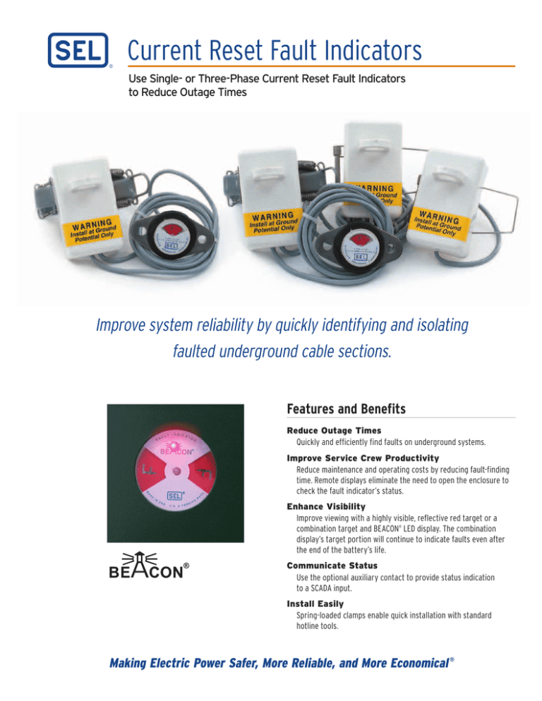
Current Reset Fault Indicators
Use Single- or Three-Phase Current Reset Fault Indicators
to Reduce Outage Times
Improve system reliability by quickly identifying and isolating
faulted underground cable sections.
Features and Benefits
Reduce Outage Times
Quickly and efficiently find faults on underground systems.
Improve Service Crew Productivity
Reduce maintenance and operating costs by reducing fault-finding
time. Remote displays eliminate the need to open the enclosure to
check the fault indicator’s status.
Enhance Visibility
Improve viewing with a highly visible, reflective red target or a
combination target and BEACON® LED display. The combination
display’s target portion will continue to indicate faults even after
the end of the battery’s life.
Communicate Status
Use the optional auxiliary contact to provide status indication
to a SCADA input.
Install Easily
Spring-loaded clamps enable quick installation with standard
hotline tools.
Making Electric Power Safer, More Reliable, and More Economical ®
General Description
Options
Current Reset Fault Indicators use continuous load current to
automatically reset and to maintain the energy required to respond
to a fault. Each unit includes:
• Current Sensing Unit
Senses the load and fault currents on the conductor.
• Spring Clamp Assembly
An integral split-core type transformer enables line crews to
install the unit with standard hot line tools.
• Visual Display
A reflective red target and/or a flashing red LED display
maximizes visibility during day and night.
• Weatherproof Housing
Withstands high temperatures and high moisture environments.
UV-stabilized polycarbonate housing is compact and lightweight.
Time Current Curve
• “IR” Inrush Restraint
• “A” Auxiliary Contact
• “DT” Delayed Trip (24 ms)
• “LC” Low-Current Reset (1.5 A)
• “3” Three-Phase Reset
• “N” Nonreplaceable C Battery (BEACON models only)
• “W” Window Mounting Kit (“L” display only)
Cable Preparation and Installation
TIME CURRENT CURVE FOR FAULT INDICATOR
Peak Amperes
in Multiples of
Nominal Trip
Rating
4.0
3.5
3.0
2.5
2.0
1.414
1.0
0.0
0.0
1.0
0.5
1.5
2.0
Time in Milliseconds
Option 1
Option 2
Option 3
SEL recommends double-back concentric neutral training, Option 1.
Options 2 and 3, which depict installation of the FCI directly over the
semicon, are also acceptable methods.
Underground Application
Line crews find the location of faults by isolating
the section of line between the last tripped (red)
fault indicator and the first untripped (white)
fault indicator.
Normally
open point
Fault Location
Tripped
Fault Indicator
Untripped
Fault Indicator
Fuse
Operational Specifications
Power Source
Mechanical Target—Load Current
LED Display
Replaceable Battery (standard)—
1200 flashing hours (2.4 Ah, 3.6 V
Lithium AA cell)
Nonreplaceable Battery (optional)—
3000 flashing hours (8.5 Ah, 3.6 V
Lithium C Cell)
Nominal Trip Rating
100 to 1200 A
Maximum Fault Current
25 kA for 10 cycles at 60 Hz
Trip Rating Tolerance
±10% at the calibrated OD
Mounting Diameter Ranges
0.75" to 2.10" (1.9 cm to 5.3 cm); larger
clamp options available
Trip Response Time
1 ms at trip rating (24 ms optional)
Submersibility
15 ft (4.6 m)
Reset
Automatic at minimum current
Housing
UV-stabilized polycarbonate
Minimum Current Reset
3 A standard, 1.5 A optional
Display Options
Reflective red target
Transformer Core
Vinyl-coated silicon steel
Typical Reset Time
25 seconds at 10 A and above
Combination target and BEACON LED
Three-Phase Reset
Automatically resets to the normal
untripped condition when current in
each phase exceeds 3 A
Tamperproof Bolt or BEACON Bolt
Inrush Restraint
Prevents false indication during reclosing
operations in situations when the inrush
current exceeds the nominal trip value
Inrush restraint response time: 300 ms
Temperature Range
—40° to +85°C
Dimensions
4.0 in
10.16 cm
INDICAT
OR
ULT
FA
N
N
5.2 in
13.21 cm
M
A
DE
IN
US
A U.S. & FO
GN
REI
PA
2.5 in
6.35 cm
TS
3.7 in
9.39 cm
BEACON Remote
“L” Display
2.5 in
6.35 cm
3.5 in
8.89 cm
RA
ZE
TO
EIT
RIE
MADE IN USA
U.S. & FOREIGN PATENTS
S
2.14 in
5.44 cm
SCHW
2.1 in
5.33 cm
CRSRTT
Trip Testing Tool
Test and manually trip
energized CR Fault Indicators.
R
EN
GIN
EERING
LA
BO
Standard Remote
“V” Display
2.5 in
6.35 cm
4.0 in
10.16 cm
2.98 in
7.57 cm
3.5 in
8.89 cm
MA
DE
IN
A∅
INDI
CA
C∅
2.1 in
5.33 cm
U SA
R
TO
1.5 in
3.81 cm
Tamperproof
Bolt Display
Magnet
2.5 in
6.35 cm
Three-Phase
Remote “4” Display
0.65 in
1.65 cm
Sold separately.
SEL Current Reset Fault Indicators
Ordering Information
Choose from the following options to complete the part number (example: 3 C R L 0 4 0 0 W ).
Phase Selection
Single-Phase
1
Three-Phase
3
Fault Indicator Type
Current Reset
BEACON® Current Reset
Type of Display
Integral Target Display
Standard Remote “V” Display
BEACON Remote “L” Display
Tamperproof Bolt Display
Three-Phase Remote “3” Display
BEACON Three-Phase Remote “4” Display
Nominal Trip Rating (contact factory for other ratings)
100 A
200 A
400 A
600 A
800 A
1000 A
1200 A
Options*
Inrush Restraint
Auxiliary Contact
Delayed Trip (24 ms)
Low Current Reset (1.5 A)
Three-Phase Reset Requirement
(not required on “3” or “4” displays)
Nonreplaceable C Battery (BEACON models only)
Window Mounting Kit (“L” Display only: included
with “V” Display)
CR
BCR
I
V
L
B
3
4
0100
0200
0400
0600
0800
1000
1200
IR
A
DT
LC
3**
N
W
* Not all options are available in all combinations.
** Only available on three-phase fault indicators.
Related Products
Type CRD Fault Indicator
Current reset technology coupled with the largest target display
in the industry (8.2 cm2) provides a solution for overhead and
underground applications.
Commitment to Quality
Five-year warranty, no questions asked.
Field application assistance available.
© 2009—2011 by Schweitzer Engineering Laboratories, Inc. All rights reserved. PF00046 • 20110209

