Thick Lenses
advertisement

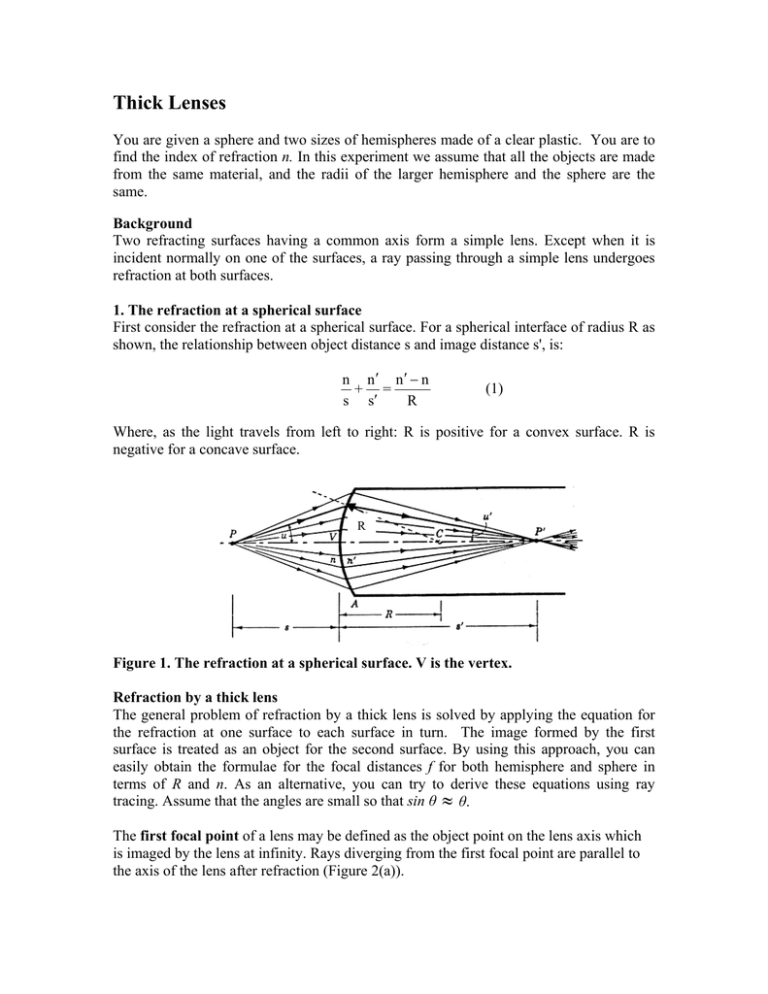
Thick Lenses You are given a sphere and two sizes of hemispheres made of a clear plastic. You are to find the index of refraction n. In this experiment we assume that all the objects are made from the same material, and the radii of the larger hemisphere and the sphere are the same. Background Two refracting surfaces having a common axis form a simple lens. Except when it is incident normally on one of the surfaces, a ray passing through a simple lens undergoes refraction at both surfaces. 1. The refraction at a spherical surface First consider the refraction at a spherical surface. For a spherical interface of radius R as shown, the relationship between object distance s and image distance s', is: n n n n + = s s R (1) Where, as the light travels from left to right: R is positive for a convex surface. R is negative for a concave surface. R Figure 1. The refraction at a spherical surface. V is the vertex. Refraction by a thick lens The general problem of refraction by a thick lens is solved by applying the equation for the refraction at one surface to each surface in turn. The image formed by the first surface is treated as an object for the second surface. By using this approach, you can easily obtain the formulae for the focal distances f for both hemisphere and sphere in terms of R and n. As an alternative, you can try to derive these equations using ray tracing. Assume that the angles are small so that sin θ θ. The first focal point of a lens may be defined as the object point on the lens axis which is imaged by the lens at infinity. Rays diverging from the first focal point are parallel to the axis of the lens after refraction (Figure 2(a)). The second focal point of a lens may be defined as the image point of an infinitely distant point object on the axis lens. Rays incident on the lens, parallel to the lens axis, pass through the second focal point after the refraction (Figure 2 (b)). Figure 2. Primary and secondary principal planes of a thick lens. A1 and A2 are the vertexes. Computation of the position of the image of a given object at a given distance from the thick lens is facilitated by determining the positions of two planes inside the lens, known as the principal planes. They are defined as follows: First principal plane: For a cone of rays diverging from the first focal point, when the incident and emergent rays are projected ahead and back, their points of intersection lie in a common plane known as the first (or primary) principal plane (Figure 2(a)) . The intersection of the first principal plane and the axis of the lens is the first principal point H1. The two deviations at the two surfaces are equivalent to a single deviation in the first principal plane. - Second principal plane: For a bundle of rays incident on a lens parallel to its axis, when the incident and emergent rays are projected ahead and back, the points of intersection lie in a common plane known as the second (or secondary) principal plane (Figure (b)). The intersection of the second principal plane and the axis of the lens is the second principal point H2. The distance from the first focal point F to the first principal point H1 is the first focal distance f, and the distance from the second principal point H2 to the second focal point F is the second focal distance f ΄. However, if the medium on both sides of the lens has the same index of refraction, which is the case if the lens is in air, the two focal lengths are equal. The equation derived for a thin lens and relating two conjugated points is: 1 1 1 s o si f (2) For the thick lens, so is the distance between the object and the first principal plane, and si is the distance between the second principal plane and the image. While applying this 2 equation to the thick lens, remember that the measurable values are the distances from the object to the vertex and from the image to the vertex (see Figure 3, below). Figure 3. Image formation by a thick lens. Lens thickness is: t = A1A2. EXERCISES Note on distance measurements: In order to measure distances along the optical bench, you’ll use the calibrated rod provided. It has 20.02 + 0.01 cm. Figure out how to use the calibrated rod, together with positions of the holders on the bench. You will not receive any other instrument (ruler, caliper or else). 1. Principal planes Sketch the locations of the second and first principal planes for the hemisphere when it is placed with its flat surface facing the light. Where are these planes located if the hemisphere is facing the light with its curved side? Sketch the locations of the principal planes for the sphere. 2. Focal distances Measure focal distances of both hemispheres (for both orientations) and that of the sphere. If you were allowed to measure the radius of the hemisphere or sphere, you could easily find the index of refraction from a single measurement of f. However, using the objects that are given to you, you can find n even without measuring R! Figure 3 shows the image formation by a thick lens. One of the ways to measure the focal distance is to find the arrangement when you observe the inverted real image of the same size as the object (magnification is m = -1). It follows from (2) that this situation takes place when so = si =2f. Note that the measurable values are the distances from the object to the vertex and from the image to the vertex. There are other ways to measure the focal distance. You can explore them as an optional exercise after you have completed the mandatory parts. 3. Using the Lens Maker’s Equation (3) and the appropriate sign for radii R1 and R2, determine the formulae for the focal distance of the hemisphere and the sphere in terms of R and n. Once you have these equations, you should be able to find n from the 3 measurements of the focal distances for the sphere and the hemisphere of the same radius. 4. “Oliver’s Law”: A student has demonstrated that the index of refraction can be found from two measurements (for the hemisphere facing light with its flat side and for the reversed hemisphere) without knowledge of R! This is "Oliver's Law", (although Oliver wanted to reject it as "obviously wrong"). Try to determine n from the measurements using only one hemispherical lens. The Lens Maker's Equation: 1 1 1 (n 1)t (n 1)( ) f R1 R2 nR1 R2 The focal distance of a ball lens (the sphere) is given by: f ball A1H1 distance: h1 f ( n 1)t nR 2 H2A2 distance: h2 f ( n 1)t nR1 nR 2(n 1) (3) (3’) (4) (4’) where R1 and R2 are the radii of the first and the second surfaces, h1 and h2 are the distances from the principal planes to the corresponding vertexes (see Figure 3), and t = A1A2 is the axial thickness of the lens (the distance between the vertexes). References E. Hecht: Optics, 4th ed., Addison Wesley 2001 Reviewed by Ruxandra Serbanescu in 2013. 4


