Introduction to Bioelectricity Part II
advertisement
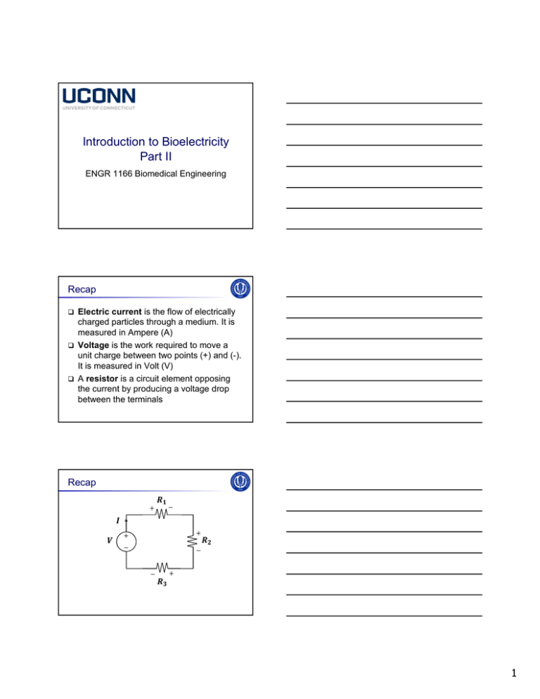
Introduction to Bioelectricity Part II ENGR 1166 Biomedical Engineering Recap Electric current is the flow of electrically charged particles through a medium. It is measured in Ampere (A) Voltage is the work required to move a unit charge between two points (+) and (-). It is measured in Volt (V) A resistor is a circuit element opposing the current by producing a voltage drop between the terminals Recap + − + + − − − + 1 Recap + − + + − − ideal voltage source (IVS) (it generates a prescribed voltage regardless of the current flow) − + + − Recap resistors + + − − − + Recap (Ohm’s Law) + − + + − − − = + = , , 2 Nodes in a circuit A node is any point on a circuit where two or more circuit elements meet + − Nodes in a circuit A node is any point on a circuit where two or more circuit elements meet Two nodes are different if their voltages are different + − Nodes in a circuit A node is any point on a circuit where two or more circuit elements meet A node is essential if 3 or more circuit elements meet in it + − 3 Kirchhoff’s current law (KCL) At any node in an electrical circuit, the sum of the currents flowing into that node is equal to the sum of currents flowing out of that node Kirchhoff’s current law (KCL) At any node in an electrical circuit, the sum of the currents flowing into that node is equal to the sum of currents flowing out of that node + = + Kirchhoff’s current law (KCL) Equivalently, at any node in an electrical circuit, the algebraic sum of the currents is equal to zero − = 4 What KCL tells us… Current cannot be lost as it flows around the circuit: net charge cannot accumulate within the circuit Any current that enters one terminal of a circuit element must exit at the other terminal of the element Current can only flow in a closed circuit KCL: example 1 = = + V − + − = Ω What is the power of each circuit element? KCL: example 1 = = + V − KCL at node A: − Ohm’s law: node A = + − − × + = Ω = 5 KCL: example 1 = = V = + − = V Power of IVS: Power of resistor: A − = Ω = => = ⁄ = A ⁄ = ⁄ = ⁄ = A KCL: example 1 Power of ICS: ⁄ = = Ω node A + KCL at node A: = − = ⁄ = ⁄ = KCL: example 1 Ohm’s law: + − KCL at node A: = = + V Ohm’s law: node A node A + = + − =− × =− × = × − =− =− =+ = Ω W W W 6 KCL: example 2 = A = . Ω + − =? − = + − = . + Ω − V + = . A − = + − =? A = . =? Ω KCL: example 2 = A = . Ω + − =? − = + − = . node A + Ω − + =? V = . A −node = B A + − = . =? Ω node C KCL: example 2 KCL at node A: − KCL at node B: − KCL at node C: − Ohm’s law: = + − − + + + = = = 7 KCL: example 2 KCL at node A: − . KCL at node B: − . KCL at node C: − Ohm’s law: = . + + . = + + = − + . = =− . A =+ . A =− . A =+ . V KCL: example 2 KCL at node A: − . KCL at node B: − . KCL at node C: − Ohm’s law: = . + + . = + + = − + . = =− . A The direction of =+ . A these two currents must be fixed! =− . A V =+ . KCL: example 2 = A = . Ω − − = . A = . A + = + − = . node A + Ω − + ≅ V −node = B A − V + = . Ω = . A node C 8 Paths in a circuit A path is a connected group of circuit elements with no repetitions + − Paths in a circuit A path is a connected group of circuit elements with no repetitions path A→ B → C→ D node A node B node C + − node D Paths in a circuit A path is a connected group of circuit elements with no repetitions A path is closed if it starts and ends at the same node + − 9 Paths in a circuit A path is a connected group of circuit elements with no repetitions A path is closed if it starts and ends at the same node node B node A + node F − node E Kirchhoff’s voltage law (KVL) In a closed path the sum of voltages across active elements must be equal to the sum of voltage drops across passive elements + − + + − − − + Kirchhoff’s voltage law (KVL) In a closed path the sum of voltages across active elements must be equal to the sum of voltage drops across passive elements + − + + − − = − + + + 10 Kirchhoff’s voltage law (KVL) Equivalently, the directed sum of voltages along any closed path in a circuit is zero + − + + − − = − − + KVL in practice… Choose a start node in the closed path + − + + − − − + KVL in practice… Explore the closed path clockwise until the start node is reached again + − + + − − − + 11 KVL in practice… For every circuit element encountered, put down the voltage. The sign of the voltage is the sign at the first terminal encountered + − + + − − − + + KVL: example + = V − = − = Ω + + − + = Ω = A − What is the power of each circuit element? KVL: example + = V − = Ω + + − = Ω = A − 12 KVL: example + = V − = Ω + + − = path 1 KVL at path 1: Ohm’s law: = + ; − KVL: example + = V Ω + path 1 KVL at path 1: KCL at node A: − + − A node A Ω = = = = + − A − − = = Ω − − = + = KVL: example KVL at path 1: KCL at node A: Ohm’s law: − = + − − ; + = = = 13 KVL: example KVL at path 1: KCL at node A: Ohm’s law: − = + − − + ; = = = =+ . A =+ . A =+ V =+ V KVL: example + = V = Ω = + + − =− =− − = =− =− Ω W W A − = = =+ =+ W W Using KCL/KVL in problem solving Identify unknowns Label each current and assign a direction to it. Then, identify the polarity of each voltage Choose the nodes and closed paths Apply KCL to nodes and KVL to closed paths. Remember: the number of independent equations must match the number of unknown Solve the equations 14 Resistance in electronic components Resistors are made as small electronic components The resistance of the component is reported on the case by using bands of different color (color code) Resistance in electronic components On a resistor, four color bands encode the resistance Resistance in electronic components On a resistor, four color bands encode the resistance 15 Resistance in electronic components The resistance is read as: = × Ω Resistance in electronic components The resistance is read as: = × Ω The tolerance is: ± % Resistance in electronic components In figure: = × Ω The tolerance is: ± % 16

