Fully Inorganic Electrodeposition of Pure Aragonite Prismatic
advertisement
Subscriber access provided by UNIV PARIS SUD 11
Article
Fully Inorganic Electrodeposition of Pure Aragonite
Prismatic-like Textured Layers on Titanium Foils
C. Krauss, D. Chateigner, and O. Gil
Cryst. Growth Des., 2008, 8 (12), 4378-4382 • Publication Date (Web): 30 September 2008
Downloaded from http://pubs.acs.org on December 10, 2008
More About This Article
Additional resources and features associated with this article are available within the HTML version:
•
•
•
•
Supporting Information
Access to high resolution figures
Links to articles and content related to this article
Copyright permission to reproduce figures and/or text from this article
Crystal Growth and Design is published by the American Chemical Society. 1155
Sixteenth Street N.W., Washington, DC 20036
Fully Inorganic Electrodeposition of Pure Aragonite Prismatic-like
Textured Layers on Titanium Foils
C. Krauss,* D. Chateigner, and O. Gil
CRISMAT-ENSICAEN, CNRS UMR 6508, UniVersité de Caen Basse-Normandie,
Bd. M. Juin 14050 Caen, France
CRYSTAL
GROWTH
& DESIGN
2008
VOL. 8, NO. 12
4378–4382
ReceiVed October 16, 2007; ReVised Manuscript ReceiVed July 24, 2008
ABSTRACT: This work shows the capabilities of a specific method to synthesize pseudo-hexagonal prismatic-like layers on titanium
foils without any organic matrix intervention, in constrast to mollusc shell growth. Using an electrochemical method of deposition,
pure aragonite layers are obtained, which exhibit good texture strengths and pseudo-hexagonal crystals. The aragonite crystals grow
with the c-axes orthogonal to the titanium foil surface without in-plane orientation, which resembles textures exhibited in nacre
layers of some gastropods such as Haliotis haliotis with however lower texture strengths. It turns out that if organic materials can
magnify textural characteristics in many aragonite-based layers, the inorganic influence is intrinsically large. This work will serve
as a basis for mimicking synthetic hybrid layers by electrochemistry targeting osteoinductivity, with the view of substituting actual
biocompatible, but inert, implants, and exemplifies the inorganic role played in the growth process of natural shells.
Introduction
Biomineralization of calcium carbonate-based living tissues
remains controversially understood.1 A tremendous amount of
work has been dedicated to the understanding of mollusc shell
growth. In mollusc shells, it is generally admitted, after the
pioneering works of Weiner and co-workers,2 that animal
organic molecules (proteins, glycoproteins, polysaccharides, etc.)
promote calcification and induce the development of strongly
preferred orientations of the inorganic entity. For instance, in
nacre, organization from the crystallography viewpoint is a
matter of controversy. Crystallites orientation may be induced
by the organic matter3 or in a layer epitaxy growth,4 but most
probably crystals grow (and orient) by ionotropy onto the
organic matrix.5 Mollusc shells are mostly composed of
aragonite and calcite layers, among which nacre layers have
attracted much interest because of their excellent mechanical6
and high osteoinductive7,8 properties leading scientists to search
for a mimic of its complex architecture.9 Nacre is a biocomposite
containing 95 vol% of quasi-hexagonal aragonite platelets,10
0.4-1.2 µm thick and 5-10 µm across arranged in a highly
regular array, staggered in successive laminae and separated by
a 5 vol% protein-polysaccharide complex-layered matrix.11-14
However, we could not find in the literature composites with
synthetic aragonite as quasi-hexagonal crystal shapes, although
a lot of works are dedicated to the calcite crystal shape
modifications or control by organic species and polyelectrolyte15
and to the aragonite-calcite equilibrium changes under additive
variations.16
In view of medical applications as orthopedics, working with
titanium substrates appears to be essential because of its high
strength, inertia, and immunity to corrosion by all body fluids
and tissue. However, implants using pure titanium prostheses
are subjected to bone resorbtion. Radiographic evidence was
even reported indicating a loss of fixation at the implant-bone
interface, probably due to accumulation of Ti particles acting
on the bone-remodelling process and impacting both long- and
short-term implant-fixation strengths.17 On the other hand, Maya
Indians of Honduras already used nacre for dental implants 2000
* To whom correspondence should be addressed. E-mail: christopher.krauss@
ensicaen.fr.
years ago.18 In modern orthopedic medicine, aragonite of
Pinctada maxima stimulates bone growth by human osteoblasts.19
We report here a specific technique to mimic hexagonal-like
aragonite crystals in a textured manner on titanium substrates
similar to those found in some molluscan shell layers. We use
the capabilities of electrodeposition to coat medical-grade
titanium substrates, in which parameter variation provides an
easy monitoring of crystal shape and orientation, to demonstrate
the at least partial nonorganic nature of crystal growing of related
mollusc shell layers.
Experimental Section
Electrochemical Deposition. To obtain nacre-like deposits, we use
a conventional three-electrodes cell monitored by a VersaStatII (Princeton Applied Research) potentiostat with a saturated calomel reference
electrode and artificial seawater electrolyte (ASTM-D1141 standard).
A platinum counter electrode ensures current flow and homogeneity
on the ultrasonically cleaned titanium working electrode, using a specific
protocol for reproducibility.20,21 We used medical grade titanium
(Ti6Al4V) as substrates for our deposits. Under application of a specific
negative potential, oxygen and water reduction generate calcium
carbonate precipitation on the titanium foil. Due to the high concentration of each component in the electrolyte and to the magnetic bar
stirring, we can assume that the electrochemical deposition method used
makes enough ions for continuous concentration of the chemical species
which are involved in the depositing reactions at the electrolyte/workingelectrode interface. This technique enables the monitoring of chemical
reactions influencing the aragonite layer deposition on the working
electrode. A typical intensity versus potential diagram (Figure 1)
exhibits two main potential domains corresponding to oxygen reduction
(O2 + 2H2O + 4e- f 4OH-) and to water reduction (2H2O + 2e- f
2OH- + H2). The oxygen reduction domain is optimal for calcium
carbonate deposition because in this range a high pH zone is created
near the titanium working electrode which generates precipitation.
Calcium carbonate precipitates on the working electrode through the
following reactions in aqueous environment: NaHCO3 f Na+ +
HCO3-, CaCl2 f Ca2+ + 2Cl-, HCO3- + OH- f CO32- + H2O,
Ca2+ + CO32- f CaCO3 (solid). At negative potentials typically less
than -0.35 V, water reduction occurs with H2 release at the workingelectrode surface favoring large film porosity and pull off. At potentials
larger than -1 V, titanium reduction and oxidation take place.
Scanning Electron Microscopy. The microstructure of the layers
was observed either using a XL 30 FEG Philips or Zeiss Supra 55
scanning electron microscope in the backscattering image mode at 10
10.1021/cg701019c CCC: $40.75 2008 American Chemical Society
Published on Web 09/30/2008
Aragonite Textured Layers on Titanium Foils
Crystal Growth & Design, Vol. 8, No. 12, 2008 4379
Figure 1. Intensity vs potential diagram used to adjust the experimental potentials around the frontier between water and oxygen reduction.
keV. To confirm the chemical composition of the deposits an Inca
Oxford energy dispersive spectrometer was used.
Texture-Phase Analysis. For texture and phase analysis of the
layers, we used a 4-circles diffractometer equipped with a 120° curved
positioned sensitive INEL detector.22 The texture scans were measured
for the tilt angle χ in the 0°-60° range and in the 0°-360° range for
the azimuth φ using increments of 5° for both angles. Using our
diffractometer, a full 2θ diagram is measured for each (χ,φ) orientation
of the sample, using 300 s of counting time. It results in 936 diagrams,
each of them getting the same intensity as for a point-by-point
measurement (with a point detector) with 300 s of integration at each
point. The diagram set is then treated using the Rietveld-based software
MAUD23 within the combined analysis formalism.24 Such an approach
gives access to the mean deposit thickness, the structure, the phase
fractions and texture of each phase and the crystallite mean sizes.
Results for texture investigations are presented here as pole figures for
the main aragonite crystal directions, that is, <100> and <001>. In
the deposit pole figures, the normal to the film plane corresponds
to the normal of the pole figures. In the Haliotis pole figures, the
vertical, horizontal, and normal directions correspond to the growth,
margin, and normal directions of the shell.25
Calcium carbonates crystallize in three allotropic forms: the much
stable calcite form (R3jc, trigonal), the less stable Vaterite (P63/mmc,
hexagonal), and the metastable aragonite (Pmcn, orthorhombic).
Because of the small difference between the Gibbs energies of calcite
and aragonite (∆G°cfa ) -1 kJ/mol), it becomes relatively easy to
obtain only Aragonite by playing on the experimental parameters of
electrodeposition as electrolyte temperature, composition, cell steering,
etc.
Electrochemical Deposition of Aragonite. Each cited deposition
parameters was optimized with a focus on oriented aragonite deposits.
At high temperatures (higher as 50 °C) and high negative potentials
(less than -1.5 V), the H2 gaseous emission at the working interface
induces high porosity of the deposit (Figure 2). After optimization of
these parameters,26 a typical potential of -1.4 V was chosen to operate
deposition. A gross optimization of deposition conditions provides in
3 h typically 5 µm thick, pure aragonite deposits (Figure 3). Energy
dispersive X-ray scattering analysis confirms the unique presence of
calcium, carbon, and oxygen elements, in the CaCO3 composition
without all other elements from the seawater electrolyte such as Mg,
and permits stirring adjust close to higher orientation in crystal growth.
The increase of concentration of Mg in the electrolyte suppressed
vaterite in the deposit and caused instability in calcite growth which
induced preferentially aragonite deposit.27 While usual cauliflower
aragonite crystal shapes are observed for most of the deposition
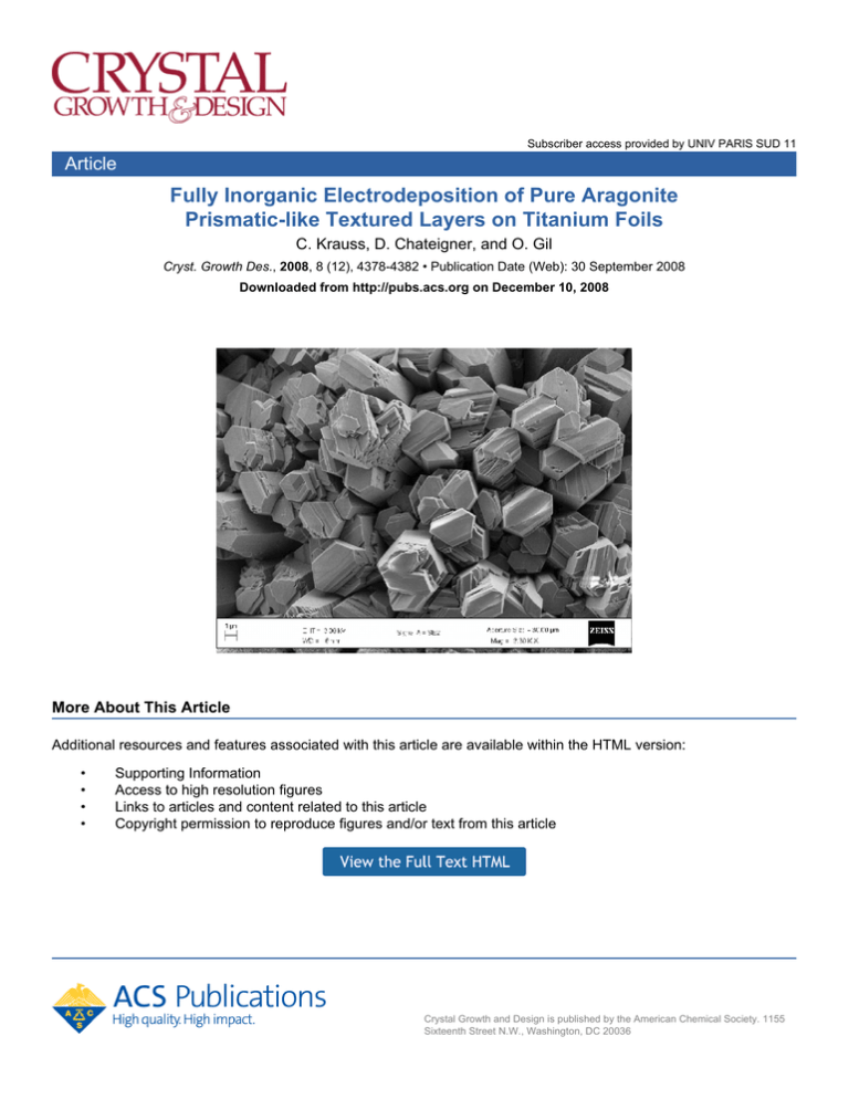
conditions (Figure 4a), interestingly hexagonal aragonite crystals are
formed (Figure 4b,c) in the following condition ranges: (pH ) [8.2,
8.3]; potential ) [-1.45 V, -1.35 V]; [MgCl2] ) [0.026 M, 0.029
Figure 2. H2 gaseous emission at the electrolyte/working-electrode
interface induces high porosity and disorientation in crystal growth.
M]; T ) [38 °C, 45 °C]). The aragonite crystals are approximately 2
µm in width, appear as columnar growth at a small magnification
(Figure 4b), and are homogeneously distributed at the surface of the
titanium plate on several cm2. However at large magnifications, the
columns do show internal porosities at the 100 nm scale. Interestingly,
these porosities are arranged parallel to the cross sections of the columns
and look like cracks (Figure 4c,d). In the conditions used, the system
is placed quite out of equilibrium, at relatively large temperatures and
at a potential close to gaseous H2 formation, which corresponds to
aragonite metastable phase formation. Simultaneously, the Mg2+ species
of the electrolyte prevent calcite stabilization in favor of aragonite. The
equilibrium is shifted enough to create aragonite twins, known in this
phase to promote quasi-hexagonal crystal shapes.28,29 Crystals grow
on the surface with hexagon planes parallel to the plate surface (Figure
4b) for most of them.
There is no clear speciation model to be described at the present
time under our deposition conditions. Our method could result in
processes similar to those described by Neville and Morizot.30 These
authors, in the context of cathodic protection, observed a first brucitelike layer at the interface with the steel electrode, before calcium
carbonate crystallization occurs. Our first EDX analyses indeed revealed
nucleation of an Mg-rich phase at the beginning of the deposition, but
could not detect any Mg-integration in the latter aragonite crystals.
However, we are using strongly negative potentials compared to these
studies, and our titanium electrode could have a strong impact on the
4380 Crystal Growth & Design, Vol. 8, No. 12, 2008
Krauss et al.
Figure 6. X-ray pole figures recalculated from the ODF (a) (002) and
(b) (200) pole figures of the inner nacre layer of the gastropod Haliotis
haliotis.
Figure 3. Experimental X-ray diffraction diagram (dots) of a typical
nacre-like film. Note the enhanced (002) line compared to a perfect
powder, indicating the pronounced (00l) orientation. Only lines from
aragonite are observed. The diagram (line) corresponds to a Rietveld
fit without texture correction.
pendicularly to the substrate plane, as seen on the {002} pole
figure (Figure 5a). The (200) pole figure (Figure 5b) indicates
that the a- and b-axes are randomly distributed around c, in a
so-called <001> fiber texture. The pseudohexagons on the
surface of the films then correspond to the (a,b) planes of
aragonite, while the c-axes are perpendicular to the hexagons.
Our film’s texture reaches orientation densities around 5 times
the random distribution (5 m.r.d.) along the fiber axis (maximum
of the (001) pole figure). Such texture strengths are however
far from aragonite orientation strengths in natural nacres of
gastropods such as Haliotis haliotis. In these latter species, nacre
exhibits highly intense diffraction peaks (Figure 6) with a more
pronounced 002 line than on our films and some absent
reflections because of the strong texture present in the layer.
The X-ray quantitative texture analysis reveals a very large
texture strength of this inner columnar nacre layer (Figure 6a,b),
with a maximum orientation density of the (002) pole figure
around 92 m.r.d.. Such a texture strength is among the strongest
in mollusc shells.25 Furthermore, the a- and b-axes of aragonite
in this mollusc shell are, as in our films, at random around c, in
a <001> fiber texture arrangement. From a textural point of
view, electrochemical deposition can then provide strong
mimicking of natural gastropod shells.
Discussion
Figure 4. SEM backscattering images of aragonite deposits on titanium
foils for (a) nonoptimized deposition conditions showing typically
cauliflower-shaped aragonite, (b) optimized conditions with nacre-like
pseudohexagonal-shaped crystals, and (c) same as (b) using a larger
magnification.
Figure 5. X-ray pole figures recalculated from the ODF. (a) (002) and
(b) (200) pole figures of our film on Ti foil.
deposition process. Local Raman investigations will be performed to
try to investigate further in this direction.
Results and Discussion
X-ray Characterization Results. A X-ray quantitative
texture analysis24 was performed on the films exhibiting crystals
closest to hexagons (Figure 5a,b). Clearly, a strong texture is
observed with c-axes of aragonite prominently oriented per-
Nacre layers are observed throughout Mollusca, exhibiting
rather uniform crystal shapes and sizes. Following the terminology,10 based on subunits observed in SEM section images, nacre
can be classified in two different arrangements, columnar nacres
(CN) or sheet nacres (SN) depending on the stacking mode of
the individual tablets. Columnar nacre has platelets with
coinciding centers, while in sheet nacre deposition takes place
in a “brick-wall” pattern. Sheet nacres are mostly observed as
inner layers of bivalves and monoplacophora. They exhibit the
so-called “double-twinned” textures in the formers, with relatively small amounts of twins depending on the species, and
fiber textures in the latter.25,31 Columnar nacres are in majority
observed in the inner layers of gastropods and cephalopods, with
fiber textures and highly “double-twinned” textures, respectively.
The textures observed in our films are then similar to the ones
observed in columnar nacre of some gastropods (e.g., Tectus
niloticus, Haliotis haliotis) and in sheet nacres of some
monoplacophora (e.g., Rokopella zographi). The difference in
texture strength, between our samples and natural nacres, can
be associated to organic driven processes like the one giving a
brick-wall sheet arrangement, though electrodeposition parameters could still be optimized to render larger texture strengths.
Nevertheless the crystal shapes already are pseudohexagonal.
It then seems that such crystal shapes do not need exclusively
organic intervention but can be crystallized under out-ofequilibrium (large potential and cationic compositions) crystallization mechanism. This fact does not represent the first
observation of the mineral influence on aragonite growth, since
Aragonite Textured Layers on Titanium Foils
for instance Checa et al.,32 developed the “progressive organisation” model to partially account for a- and b-axes organization
in bivalve nacres. Our texture and crystal morphology observation demonstrates there is a priori no need for organic material
to play a role in the aragonite orientation in fiber-like gastropod textures (nacres and prismatic layers), except to enhance
their texture strength. Furthermore, the intrinsic capability of
aragonite to crystallize as twinned hexagons33 is clearly
exhibited in our purely inorganic films, twins being known to
accommodate slightly larger energetic states of crystals.
Our elaboration conditions then provide enough perturbation
to the equilibrium to promote twin formation, and smoothly
enough to avoid cauliflower crystals. These observations would
explain why organic amounts as small as 5 vol% are able to
influence and control shell growths. Indeed, it might be difficult
to understand how such smoothly textured organic material as
observed by Weiner et al.4 could induce such strong textures
as observed in natural nacres, without inorganic capabilities to
favor the process. Once nucleated on organic species, crystal
growth takes place and the resulting crystal shapes behave
depending on external conditions. These conditions can be
purely thermodynamic (pressure, salinity, etc.) and/or provided
by the organic entities (molecular nucleation sites, geometric
configurations, etc.).34 They can either promote specific crystal
shapes (e.g., quasi-perfect nacre hexagons observed in large
bivalves like Pinctada margaritifera), or restrict crystal growth
inside organically constructed cells (e.g., nacre platelet domains
variations as observed in Haliotis species29). Thermodynamic
conditions are not believed generally to influence considerably
shell growth. For instance, textures and crystal shapes of inner
nacre layers of Bathymodiolus thermophylus35 and Mytilus edulis
are quite identical, although these two species live at considerably different pressures, which points toward a large organic
influence. However, our experiments show that under given
conditions, relatively small parameter changes (temperature, Mg
concentration, etc.) can drastically modify both texture and
crystal shapes and sizes. Since the observed lateral sizes of our
synthetic aragonite columns are comparable to the ones found
in natural species, one can argue there is a crystallographically
intrinsic limited width of these columns that is used during shell
growth by organic entities. Indeed, from an energetic point of
view, it will become harder to accommodate twins when the
lateral size of nacre columns increases, resulting either in
creation of different columns or in different twinning arrangements of the columns as observed by Mutvei.29 All the
thermodynamically induced modifications are limited in magnitude (aragonite crystals grow generally acicular or as platelets,
with or without twins) but can control ultrastructural variabilities
imposed by organic materials in mollusc shells. Lastly, the
aragonite prisms of Figure 4c show another aspect of the strong
inorganic influence in aragonite growth. Each individual prismatic column appears segmented along its length at a larger
magnification. The segments are delineated by cracks occurring
every 0.3 µm along the length of the prismatic column which
are typically about the same size as natural nacre tablets. Such
resemblance is another aspect of the growing process of our
films that goes toward the hypothesis of an inorganically driven
crystallization in natural nacres. Such cracks accommodate
partially twin-induced stresses along the columns. Once created,
a given crack gives rise to free surfaces on which organic
molecules could adsorb and permit further crystal nucleation.
At this point, the adsorbed molecule can even induce a slightly
different orientation of the next tablet, for instance, as the
rotation around the c-axes observed from tablet to tablet in
Crystal Growth & Design, Vol. 8, No. 12, 2008 4381
natural species.36 In this new understanding of nacre development, organically driven crystallization relies on crack formation.
However, this does not mean organic influence is absent. The
latter still promotes much stronger global organization of crystals
in between and inside nacre columns, but rather organic
influence needs cracks to exist, at least along the columns. For
instance, in calcite prism layers of bivalves such as Crassotrea
gigas,37 the prisms do not show any evidence of cracks, but
are still macroscopically oriented.
Conclusion
Pure aragonite deposits on titanium substrates were elaborated
using an electrochemical technique. The deposits are textured
with their c-axes orthogonal to the titanium surface, a- and
b-axes being at random around c, giving rise to <001> fiber
texture patterns. Under given conditions, a pseudohexagonal
cross-section of oriented aragonite rods is observed, due to the
intrinsic aragonite twin symmetry. The observed textures of the
deposits, together with the pseudohexagonal segmented prismatic crystal shapes, mimick prismatic natural layers found in
gastropods columnar layers. The fully inorganic character of
the deposition technique and the strong resemblance of the
microstructures of the films with natural layers impose a stronger
control of molluscan architectures by inorganic crystallization
than previously understood.
References
(1) Mann, S. Nature 1988, 332, 119–124.
(2) Weiner, S.; Traub, W. In Structural Aspects of Recognition and Assembly
in Biological Macromolecules; Balaban, M., Sussman, J. L., Traub,
W., Yonath, A., Eds.; Balaban ISS: Rehovot, IS, 1981; pp 467-482.
(3) Weiner, S.; Traub, W. FEBS Lett. 1980, 111, 311–316.
(4) Weiner, S.; Talmon, Y.; Traub, W. Int. J. Biol. Macromol. 1983, 5,
325–328.
(5) Nassif, N.; Pinna, N.; Gehrke, N.; Antonietti, M.; Jäger, C.; Cölfen,
H. Proc. Natl. Acad. Sci. U. S. A. 2005, 102, 12653–12655.
(6) Currey, J. D. Proc. R. Soc. B 1977, 196, 443–463.
(7) Lopez, E.; Vidal, B.; Berland, S.; Camprasse, S.; Camprasse, G.; Silve,
C. Tissue Cell 1992, 24, 667–679.
(8) Atlan, G.; Balmain, N.; Berland, S.; Vidal, B.; Lopez, E. C. R. Acad.
Sci III-Vie 1997, 320, 253–258.
(9) Sellinger, A.; Weiss, P. M.; Nguyen, A.; Lu, Y.; Assink, R. A.; Gong,
W.; Brinker, C. J. Nature 1998, 394, 256–260.
(10) Caspi, E. N.; Pokroy, B.; Lee, P. L.; Quintana, J. P.; Zolotoyabko, E.
Acta. Crystallogr. B 2005, 61, 129–132.
(11) Carter, J. G.; Clark, G. R. In Molluscs, notes for a short course; Bottjer,
D. J.; Hickman, C. S.; Ward, P. D.; Broadhead, T. W.; Department of
Geological Sciences Studies in Geology; University of Tennessee:
Knoxville, 1985; pp 50-71.
(12) Nakahara, H. In Mechanisms and Phylogeny of Mineralization in
Biological Systems; Suga, S.; Nakahara, H.; Springer: Berlin, DE,
1991; Chapter 4.2, pp 343-350.
(13) Nakahara, H. In Biomineralization and Biological Metal Accumulation;
Westbroek, P.; Jong, E. W.; Reidel: Dordrecht, NL, 1983; pp 225230.
(14) Cartwright, J.H. E.; Checa, A. G. J. R. Soc. Interface 2007, 4, 491–504.
(15) Wang, T.; Cölfen, H.; Antonietti, M. J. Am. Chem. Soc. 2005, 127,
3246–3247.
(16) Hosoda, N.; Sugawara, A.; Kato, T. Macromolecules 2003, 36, 6449–
6452.
(17) Choi, M. G.; Koh, H. S.; Kluess, D.; O’Connor, D.; Mathur, A.;
Truskey, G. A.; Rubin, J.; Zhou, D. X.; Sung, K. L. Proc. Natl. Acad.
Sci. U. S. A. 2005, 102, 4578–4583.
(18) Bobbio, A. Bull. Hist. Dent. 1972, 20, 1–6.
(19) Silve, C.; Lopez, E.; Vidal, B.; Smith, D. C.; Camprasse, S.;
Camprasse, G.; Couly, G. Calcif. Tissue Int. 1992, 51, 363–369.
(20) Barbiche, C.; Deslouis, C.; Festy, D.; Gil, O.; Refait, P.; Touzain, S.;
Tribollet, B. Electrochim. Acta 2003, 48, 1645–1654.
(21) Deslouis, C.; Festy, D.; Gil, O.; Rius, G.; Touzain, S.; Tribollet, B.
Electrochim. Acta 1998, 43, 1891–1901.
4382 Crystal Growth & Design, Vol. 8, No. 12, 2008
(22) Morales, M.; Chateigner, D.; Lutterotti, L.; Ricote, J. Mater. Sci. Forum
2002, 408, 113–118.
(23) Lutterotti, L.; Matthies, S.; Wenk, H. R. In Proceedings of the Twelfth
International Conference on Textures of Materials; Szpunar, J. A.,
Ed.; NRC Research Press: Ottawa, CA, 1999; pp 1599-160.
(24) Chateigner, D. Combined Analysis: Texture-Structure-Phase-StressReflectivity Characterisation Using X-ray and Neutron Scattering,
2004;http://www.ecole.ensicaen.fr/∼chateign/texture/combinedanalysis.
PDF.
(25) Chateigner, D.; Hedegaard, C.; Wenk, H. R. J. Struct. Geol. 2000,
22, 1723–1735.
(26) Krauss, C.; Chateigner, D.; Gil, O. Electrodeposition of nacre-like
layers. Electrochim. Acta, submitted.
(27) Chen, T.; Neville, A.; Yuan, M. J. Cryst. Growth 2005, 275, 1341–
1347.
(28) Bragg, W. L. In Atomic Structures of Minerals; Cornell University of
Press: Ithaca, NY, 1937; pp 114-126.
(29) Mutvei, H. The Mechanisms of Biomineralization in Animals and Plant;
Omori, M.; Watabe, N., Eds.; Tokai University Press: Tokyo, 1980;
pp 49-56.
Krauss et al.
(30) Neville, A.; Morizot, A. P. J. Cryst. Growth 2002, 243, 490–502.
(31) Checa, A. G.; Rodriguez-Navarro, A. B. Biomaterials 2005, 26, 1071–
1079.
(32) Checa, A. G.; Okamoto, T.; Ramı́rez, J. Proc. R. Soc. London B 2006,
273, 1329–1337.
(33) Fleming, S. D.; Parkinson, G. M.; Rohl, A. L. J. Cryst. Growth 1996,
178, 402–409.
(34) Checa, A. G.; Okamoto, T.; Ramirez, J. Proc. R. Soc. B 2006, 273,
1329–1337.
(35) Schaffer, T. E.; Ionescu-Zanetti, C.; Proksch, R.; Fritz, M.; Walters,
D. A.; Almqvist, N.; Zaremba, C. M.; Belcher, A. M.; Smith, B. L.;
Stucky, G. D.; Morse, D. M.; Hansma, P. K. Chem. Mater. 1997, 9,
1731–1740.
(36) Dalbeck, P.; England, J.; Cusack, M.; Lee, M. R.; Fallick, A. E. Eur.
J. Mineral. 2006, 24, 601–609.
(37) Chateigner, D.; Morales, M.; Harper, E. M. Mater. Sci. Forum 2002,
408-412, 1687–1692.
CG701019C
