Assembly Instructions
All Terrain® Mobile Pedestal
February 2014
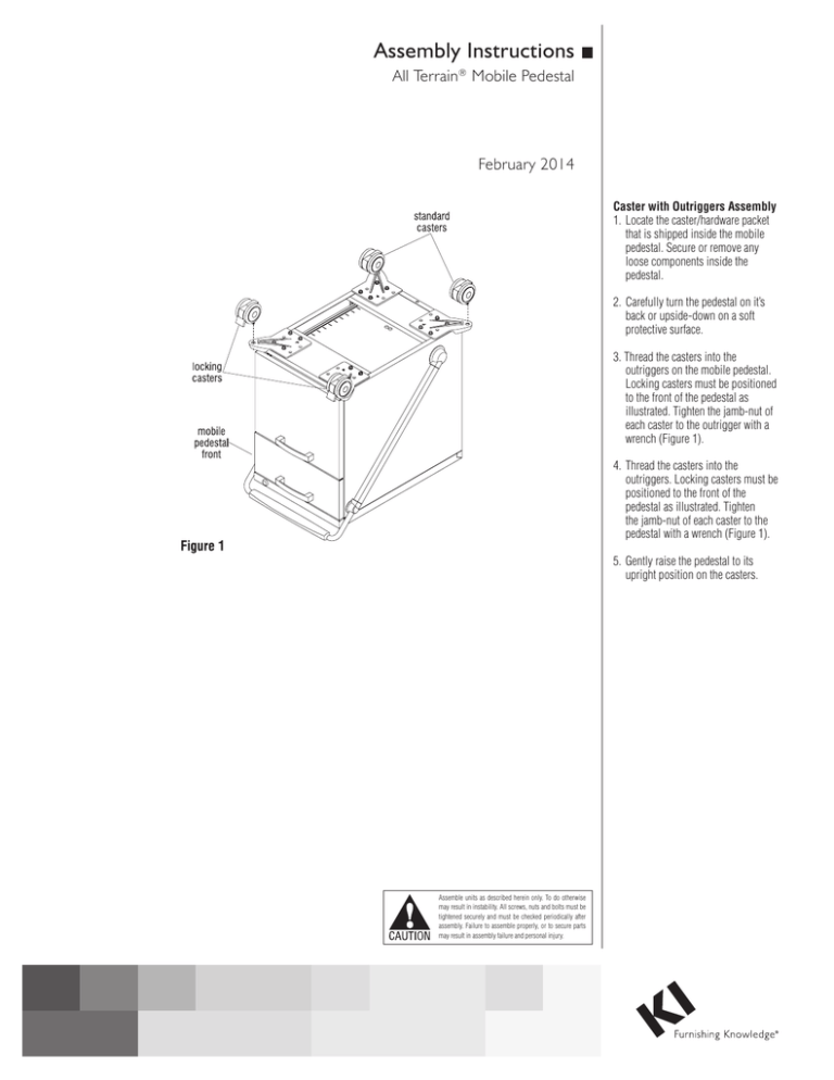
Caster with Outriggers Assembly
1. Locate the caster/hardware packet
that is shipped inside the mobile
pedestal. Secure or remove any
loose components inside the
pedestal.
2. Carefully turn the pedestal on it’s
back or upside-down on a soft
protective surface.
3. Thread the casters into the
outriggers on the mobile pedestal.
Locking casters must be positioned
to the front of the pedestal as
illustrated. Tighten the jamb-nut of
each caster to the outrigger with a
wrench (Figure 1).
4. Thread the casters into the
outriggers. Locking casters must be
positioned to the front of the
pedestal as illustrated. Tighten
the jamb-nut of each caster to the
pedestal with a wrench (Figure 1).
5. Gently raise the pedestal to its
upright position on the casters.
Assemble units as described herein only. To do otherwise
may result in instability. All screws, nuts and bolts must be
tightened securely and must be checked periodically after
assembly. Failure to assemble properly, or to secure parts
may result in assembly failure and personal injury.
All Terrain® Mobile Pedestal
Assembly Instructions
Assemble units as described herein only. To do otherwise
may result in instability. All screws, nuts and bolts must be
tightened securely and must be checked periodically after
assembly. Failure to assemble properly, or to secure parts
may result in assembly failure and personal injury.
Inboard Caster Assembly
1. Locate the caster/hardware packet
that is shipped inside the mobile
pedestal. Secure or remove any
loose components inside the
pedestal.
2. Carefully turn pedestal
upside-down on a soft
protective surface (Figure 2).
Note: Locking casters must be
positioned to the front of the
pedestal.
3. Thread the casters into the
bottom of the mobile pedestal.
Locking casters must be
positioned to the front of the
pedestal as illustrated. Tighten
the jamb-nut of each caster to
the bottom of the pedestal with a
wrench (Figure 2).
4. Gently raise the pedestal to it’s
upright position on the casters.
Flush Mount Pull Assembly
1. Locate the pull/hardware packet
that is shipped inside the mobile
pedestal.
2. Using two 4mm x 10mm screws,
fasten the pull to the drawer front
as illustrated (Figure 3).
Note: If installing a pull on a
laminate door, use two
4mm x 25mm screws per pull.
Black caps are not required.
2
All Terrain® Mobile Pedestal
Assembly Instructions
Assemble units as described herein only. To do otherwise
may result in instability. All screws, nuts and bolts must be
tightened securely and must be checked periodically after
assembly. Failure to assemble properly, or to secure parts
may result in assembly failure and personal injury.
Landing Pad Assembly
Note: Before beginning landing
pad assembly, it is recommended
that the top drawer be removed if
there is a drawer installed directly
below the landing pad. See
instructions below.
5. From inside the cabinet, locate
the 1/4-20 x 4” bolts inserted
through the top and place a 1/4”
flat washer and 1/4-20 k-lock nut
onto each bolt. Tighten nuts to
secure landing pad to cabinet top
(Figure 4).
1. The landing pad top is shipped
with two bolts securing it to the
mobile pedestal. Remove the two
bolts and properly dispose of
them. Gently set the top aside,
assuring it will not get damaged/
scratched.
6. Reinstall any drawers that were
removed to assemble landing pad.
2. Locate the hardware pack for the
Landing Pad and identify the
parts by referencing Figure 4.
Begin assembly by inserting four
1
/4-20 x 4” bolts into four (upper)
landing pad mount bushings.
Secure the upper bushings to
the underside of the landing pad
as illustrated using four #8 x ½”
screws (Figure 4).
2. Using a flathead screwdriver, place
the tip between the drawer body
and the suspension at a position
near the front slip connection.
With the screwdriver upright,
rotate it to pry the suspension
away from the drawer body. As
this is done, lift up on the bottom
of the drawer to separate the
connection. Repeat on the other
side of the drawer.
3. Place a lower landing pad post
bushing into the bottom of each
landing pad post and press the
four landing pad posts/lower
bushings onto the installed upper
landing pad mount bushing and
4” bolt (Figure 4).
4. Carefully position the landing pad
with installed bushings, posts
& bolts such that the four bolts
insert through the four mounting
holes in the top of the cabinet
(Figure 4).
Drawer Removal - 15” Wide
1. To remove a drawer, first empty
all of it’s contents and extend the
drawer out as far as it will go.
3. Pull the drawer slightly up and out
of the rear slip connections.
Drawer Installation - 15” Wide
1. To install a drawer, first extend the
two extensions out as far as they
will go.
2. Slide the rear slip connection
together by aligning the tab
on the suspension with the
corresponding slot on the drawer.
Firmly hold the suspension to
ensure the drawer is properly
connected. Repeat on other side
of drawer.
3. With the rear slip connections
correctly in place, the front slip
connection tabs will align and the
drawer can be pushed down into
place.
3
KI
1330 Bellevue Street
P.O. Box 8100
Green Bay, Wisconsin 54308-8100
1-800-424-2432
www.ki.com
KI is a registered trademark
of Krueger International, Inc.
© 2014 Krueger International, Inc.
All Rights Reserved
Code KI-61329R4/KI/PDF/0214

