Posey® Exit Mat Sensor
Fall Management
Exit Mat Sensor
Designed to work with Posey Fall Monitors, the Posey Exit
Mat Sensor provides caregivers an early warning of patient
attempts to exit a bed, through a doorway, or enter
“off-limit” areas. The Exit Mat Sensor is available in two
sizes for use either next to a patient’s bed, or in front of a
door.
REF
REF
8250S Exit Mat Sensor, Small - 36”L x 24”W (91 cm x 61 cm)
8250L Exit Mat Sensor, Large - 60”L x 24”W (152 cm x 61 cm)
Before You Begin
When used properly, Posey sensors and fall alarms alert
staff that a patient has applied weight to the sensor and
may be at immediate risk of falling. However, fall alarm
systems DO NOT prevent falls and are not a substitute for
good nursing care and regular visual monitoring.
• This device may not be suitable for all high fall-risk
patients. See Posey catalog for other options for such
patients.
• NEVER connect Posey sensors to other manufacturers’
alarm units.
• NEVER connect Posey Alarms to other manufacturers’
sensors.
Application Instructions:
1. Position the Exit Mat Sensor on the floor, next to the
bed, or in front of a doorway.
2. Connect the sensor to a Posey Fall Monitor.
3. Turn Fall Monitor ON.
4. Mount the Fall Monitor on the headboard or wall using
the brackets included with the Fall Monitor.
5. Tuck excess sensor cable under the corner of the mat or
out of the way to avoid a tripping hazard.
System Test:
1. Plug sensor into Alarm unit.
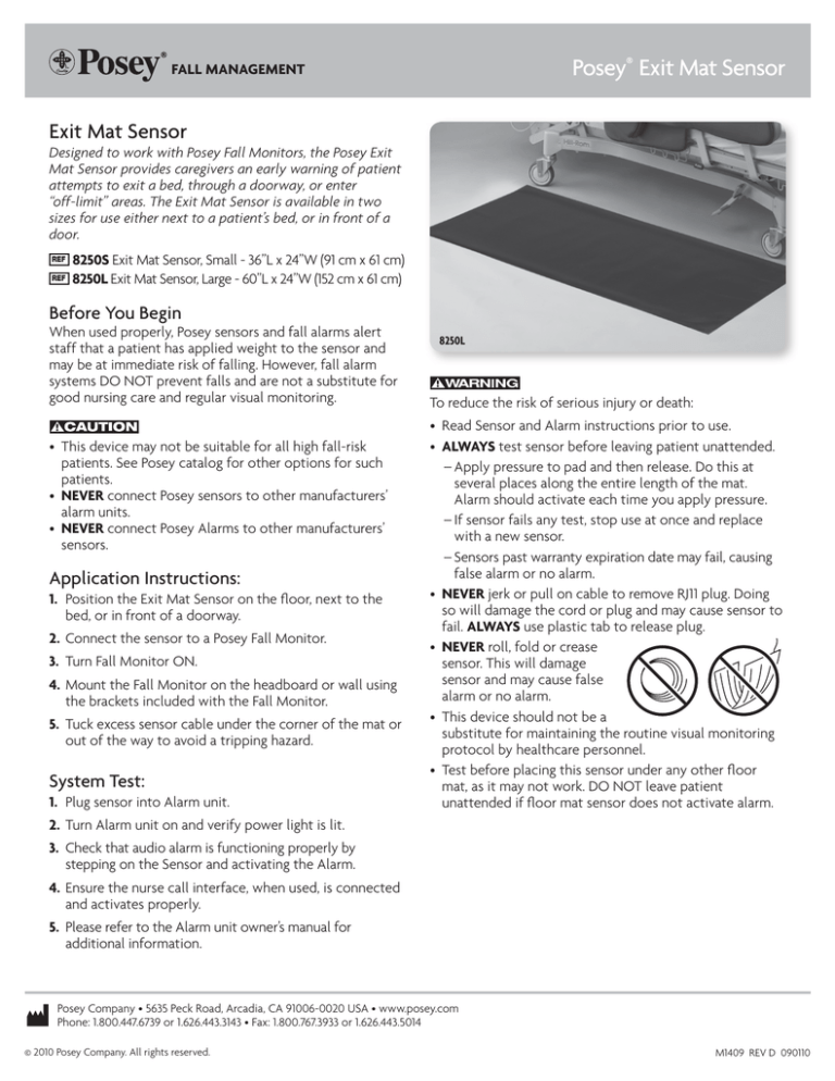
8250L
To reduce the risk of serious injury or death:
• Read Sensor and Alarm instructions prior to use.
• ALWAYS test sensor before leaving patient unattended.
–Apply pressure to pad and then release. Do this at several places along the entire length of the mat. Alarm should activate each time you apply pressure.
–If sensor fails any test, stop use at once and replace with a new sensor.
–Sensors past warranty expiration date may fail, causing false alarm or no alarm.
• NEVER jerk or pull on cable to remove RJ11 plug. Doing
so will damage the cord or plug and may cause sensor to
fail. ALWAYS use plastic tab to release plug.
• NEVER roll, fold or crease
sensor. This will damage
sensor and may cause false
alarm or no alarm.
• This device should not be a
substitute for maintaining the ­routine visual monitoring
protocol by healthcare personnel.
• Test before placing this sensor under any other floor
mat, as it may not work. DO NOT leave patient
unattended if floor mat sensor does not activate alarm.
2. Turn Alarm unit on and verify power light is lit.
3. Check that audio alarm is functioning properly by
stepping on the Sensor and activating the Alarm.
4. Ensure the nurse call interface, when used, is connected
and activates properly.
5. Please refer to the Alarm unit owner’s manual for
additional information.
Posey Company • 5635 Peck Road, Arcadia, CA 91006-0020 USA • www.posey.com
Phone: 1.800.447.6739 or 1.626.443.3143 • Fax: 1.800.767.3933 or 1.626.443.5014
© 2010 Posey Company. All rights reserved.
M1409 REV D 090110
Posey® Exit Mat Sensor (Cont.)
Fall Management
Cleaning:
• Make sure pad has no visible cuts or signs of damage.
• Dampen a clean cloth with disinfectant. Take extra care when cleaning sensor plugs.
• NEVER: use any cleaner that contains Phenol or Benzyl; immerse in liquid; or sterilize with heat.
• Dry with a clean cloth.
Storage:
• This device is designed for use in normal indoor environments.
• This device may be stored in ambient warehouse temperatures at normal humidity levels. Avoid excess moisture or high humidity
that may damage product materials.
Disposal:
Dispose of per facility policy for BIOHAZARDOUS material. Be sure to follow all laws that apply.
Warranty:
8250S - This product is warranted for one (1) year from date of first use.
8250L - This product is warranted for one (1) year from date of first use.
See Posey Catalog for Warranty details.
REF
REF
The instructions below should be performed by a trained technician or qualified biomed personnel.
Sensor RJ11 Connector Replacement
TOP - VIEW FROM TAB SIDE
BOTTOM - VIEW FROM CONTACT SIDE
1.
2.
3.
1. Strip 1/4” (0.63 cm) of the gray cable cover to expose the four thin colored wires. Do not cut through the colored wires.
2. Place RJ11 plug over the correct colored wires, as shown in the diagram above.
3. Crimp RJ11 plug using a standard RJ11 crimping tool, making sure the colored wires are secure.
Note: RJ11 phone connectors and crimping tools are available at most hardware and/or e­ lectronic parts stores.
Posey Company • 5635 Peck Road, Arcadia, CA 91006-0020 USA Phone: 1.800.447.6739 or 1.626.443.3143 • Fax: 1.800.767.3933 or 1.626.443.5014 • Web: www.posey.com

