1.888.453.8358 woodbywy.com
INSTALLATION GUIDE
FOR FLOOR AND ROOF FRAMING
TJI s31
TJI s33
TJI s47
Joists
®
®
®
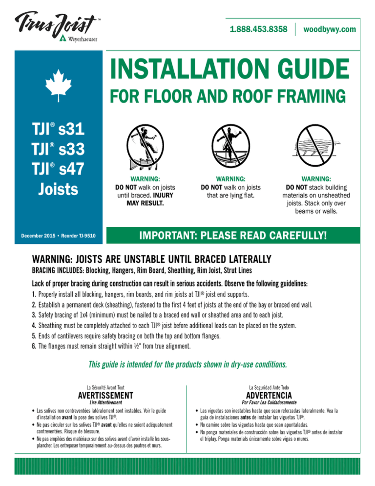
WARNING:
DO NOT walk on joists
until braced. INJURY
MAY RESULT.
December 2015 • Reorder TJ-9510
WARNING:
DO NOT walk on joists
that are lying flat.
WARNING:
DO NOT stack building
materials on unsheathed
joists. Stack only over
beams or walls.
IMPORTANT: PLEASE READ CAREFULLY!
WARNING: JOISTS ARE UNSTABLE UNTIL BRACED LATERALLY
BRACING INCLUDES: Blocking, Hangers, Rim Board, Sheathing, Rim Joist, Strut Lines
Lack of proper bracing during ­construction can result in serious accidents. Observe the following guidelines:
1.Properly install all blocking, hangers, rim boards, and rim joists at TJI® joist end supports.
2.Establish a permanent deck (sheathing), fastened to the first 4 feet of joists at the end of the bay or braced end wall.
3. Safety bracing of 1x4 (minimum) must be nailed to a braced end wall or sheathed area and to each joist.
4.Sheathing must be completely attached to each TJI® joist before additional loads can be placed on the system.
5.Ends of cantilevers require safety bracing on both the top and bottom flanges.
6.The flanges must remain straight within 1⁄2" from true alignment.
This guide is intended for the products shown in dry-use conditions.
La Sécurité Avant Tout
AVERTISSEMENT
Lire Attentivement
• Les solives non ­contreventées latéralement sont instables. Voir le guide
d’installation avant la pose des solives TJI®.
• Ne pas circuler sur les solives TJI® avant qu’elles ne soient adéquatement
contreventées. Risque de blessure.
• Ne pas empilées des matériaux sur des solives avant d’avoir installé les sousplancher. Les entreposer temporairement au-dessus des poutres et murs.
La Seguridad Ante Todo
ADVERTENCIA
Por Favor Lea Cuidadosamente
• Las viguetas son inestables hasta que sean reforzadas lateralmente. Vea la
guía de ­instalaciones antes de instalar las viguetas TJI®.
• No camine sobre las viguetas hasta que sean apuntaladas.
• No ponga materiales de construcción sobre las viguetas TJI® antes de instalar
el triplay. Ponga materials únicamente sobre vigas o muros.
1
CONTENTS
FLOOR
ROOF AND WALL
BEAM AND COLUMN
Allowable Holes—TJI® Joists. . . . . . . . . . 1
Allowable Holes—TimberStrand® LSL
Wall Studs. . . . . . . . . . . . . . . . . . . . . . . 2
Allowable Holes—TimberStrand® LSL,
Parallam® PSL, Microllam® LVL
Headers and Beams. . . . . . . . . . . . . . . . . 2
Joist Nailing Requirements
at Bearing. . . . . . . . . . . . . . . . . . . . . . . . 2
Web Stiffeners. . . . . . . . . . . . . . . . . . . . . 6
Installation Recommendations. . . . . . . . . 2
Typical Roof and Wall Framing. . . . . . . . . 6
TJI® Joist Floor Framing. . . . . . . . . . . . . . 3
Ceiling Joists. . . . . . . . . . . . . . . . . . . . . . 6
Fastening of Floor Panels. . . . . . . . . . . . . 4
Roof Details. . . . . . . . . . . . . . . . . . . . . . . 7
Rim Board Details . . . . . . . . . . . . . . . . . . 4
Framing Connectors. . . . . . . . . . . . . . . . . 8
TJI®
Floor Details. . . . . . . . . . . . . . . . . . . . 4–5
Shear Blocking and Ventilation Holes. . . . 8
Cantilever Details . . . . . . . . . . . . . . . . . . 5
TJI® Joist Nailing Requirements
at Bearing. . . . . . . . . . . . . . . . . . . . . . . . 8
Filler and Backer Blocks. . . . . . . . . . . . . 5
Beam and Column Details . . . . . . . . . . . . 9
Beam and Header Bearings . . . . . . . . . . . 9­
Build Safely
We at Weyerhaeuser are committed to working safely and want to
remind you to do the same. We encourage you to follow the recommendations of provincial regulations (www.canoshweb.org/en/) in
Canada regarding:
–Personal protective equipment (PPE) for hands, feet, head, and
eyes
– Fall protection
–Use of pneumatic nailers and other hand tools
– Forklift safety
Please adhere to the Weyerhaeuser product installation details,
including the ­installation of safety bracing on unsheathed floors
and roofs.
Web Stiffeners. . . . . . . . . . . . . . . . . . . . . 6
Framing Connectors. . . . . . . . . . . . . . . . . 8
PRODUCT IDENTIFICATION
2½"
3½"
1½"
1½"
3⁄8"
9½"
117⁄8"
14"
16"
9½"
117∕8"
14", 16"
18", 20"
7⁄16"
TJI® s47 joists
TJI® s31 and s33 joists
ALLOWABLE HOLES —TJI® JOISTS
Min. distance from Table B
Min. distance from Table A
DO NOT cut holes
in cantilever
­reinforcement.
6"
6"
DO NOT cut or
notch flange.
OR
L1
2 x D1 D1 Closely grouped round
minimum
holes are permitted if
No field
(applies to all
the group perimeter
cut holes
holes)
meets requirements for
in hatched
round or square holes
zone
1½" hole may
be cut ­anywhere
in web outside
of hatched zone
6"
L2
2 x L2
minimum
D2
6"
6"
No field
cut holes
Do not cut holes
in hatched
larger than 11/2"
zone
in cantilever
Table A—End Support
Minimum distance from edge of hole to inside face of nearest end support
Joist
TJI®
Depth
2"
3"
4"
s31
s33
s47
s31
117⁄8" s33
s47
s31
14" s33
s47
s31
16" s33
s47
18" s47
20" s47
1'-0"
1'-6"
1'-0"
1'-0"
1'-0"
1'-0"
1'-0"
1'-0"
1'-0"
1'-0"
1'-0"
1'-0"
1'-0"
1'-0"
2'-0"
2'-6"
1'-0"
1'-6"
1'-6"
1'-0"
1'-0"
1'-0"
1'-0"
1'-0"
1'-0"
1'-0"
1'-0"
1'-0"
2'-6"
3'-0"
2'-6"
1'-6"
2'-6"
2'-0"
1'-0"
1'-6"
1'-0"
1'-0"
1'-0"
1'-0"
1'-0"
1'-0"
9½"
Round Hole Size
6¼" 85⁄8" 10¾"
12¾"
5'-6"
6'-0"
6'-0"
3'-0"
3'-6"
4'-0"
2'-0"
2'-6"
2'-6"
1'-6"
1'-6"
1'-6"
1'-0"
1'-0"
1'-0"
1'-0"
1'-6"
1'-0"
1'-0"
2'-0"
1'-0"
1'-0"
1'-0"
6'-0"
1'-0"
8'-0"
1'-0"
9'-0"
1'-0"
6'-0" 9'-6"
1'-0"
4'-6" 6'-6" 10'-0" 1'-0"
6'-0"
7'-0"
7'-0"
3'-0"
4'-6"
5'-0"
2'-6"
3'-6"
3'-6"
2'-0"
1'-6"
6'-0"
8'-0"
8'-6"
3'-6"
5'-0"
5'-6"
4'-0"
2'-6"
14¾"
16¾"
2"
3"
1'-6"
2'-0"
2'-6"
1'-6"
2'-0"
3'-0"
1'-6"
1'-6"
2'-0"
1'-0"
1'-0"
1'-0"
1'-0"
1'-0"
Square or Rectangular Hole Size
4"
6¼" 85⁄8" 10¾" 12¾" 14¾" 16¾"
2'-6"
3'-0"
3'-6"
2'-6"
3'-0"
3'-6"
2'-0"
2'-6"
3'-0"
1'-6"
1'-6"
2'-6"
1'-0"
1'-0"
4'-6"
5'-0"
5'-6"
4'-6"
5'-6"
6'-6"
3'-6"
4'-6"
5'-6"
3'-0"
4'-0"
4'-6"
4'-0"
2'-6"
6'-0"
7'-0"
7'-6"
6'-0"
7'-0"
8'-0"
6'-0"
7'-0"
8'-6"
7'-0"
6'-0"
7'-6"
8'-6"
9'-6"
7'-0"
9'-0"
10'-0"
10'-6"
10'-0"
9'-6"
10'-6"
11'-0"
12'-0" 13'-6"
11'-6" 13'-0" 14'-6"
Table B—Intermediate or Cantilever Support
Minimum distance from edge of hole to inside face of nearest intermediate or cantilever support
Joist
TJI®
Depth
2"
3"
4"
Round Hole Size
6¼" 85⁄8" 10¾"
12¾"
14¾"
16¾"
s31 2'-0" 3'-0" 4'-0" 8'-6"
9½" s33 2'-6" 3'-6" 5'-0" 9'-0"
s47 1'-6" 3'-0" 4'-6" 8'-6"
s31 1'-6" 2'-0" 2'-6" 4'-6" 9'-0"
117⁄8" s33 2'-0" 3'-0" 3'-6" 5'-6" 10'-6"
s47 1'-0" 1'-0" 2'-0" 5'-6" 11'-0"
s31 1'-0" 1'-0" 1'-6" 3'-0" 5'-0" 9'-0"
14" s33 1'-0" 1'-0" 2'-0" 4'-0" 6'-6" 12'-0"
s47 1'-0" 1'-0" 1'-0" 4'-0" 7'-6" 12'-6"
s31 1'-0" 1'-0" 1'-0" 2'-0" 3'-6" 5'-6" 9'-6"
16" s33 1'-0" 1'-0" 1'-0" 2'-6" 5'-0" 7'-6" 12'-6"
s47 1'-0" 1'-0" 1'-0" 2'-0" 5'-6" 9'-0" 14'-0"
18" s47 1'-0" 1'-0" 1'-0" 1'-0" 3'-0" 6'-6" 9'-6" 14'-6"
20" s47 1'-0" 1'-0" 1'-0" 1'-0" 1'-6" 3'-6" 7'-0" 10'-6" 15'-0"
2"
3"
2'-0"
2'-0"
3'-0"
1'-6"
2'-0"
2'-0"
1'-0"
1'-0"
1'-0"
1'-0"
1'-0"
1'-0"
1'-0"
1'-0"
3'-0"
3'-6"
4'-6"
2'-6"
3'-0"
3'-6"
1'-6"
2'-0"
2'-6"
1'-0"
1'-0"
1'-6"
1'-0"
1'-0"
Square or Rectangular Hole Size
4"
6¼" 85⁄8" 10¾" 12¾"
4'-0"
4'-6"
5'-6"
3'-6"
4'-0"
5'-0"
2'-6"
3'-6"
4'-0"
1'-6"
2'-0"
3'-0"
1'-6"
1'-0"
6'-6"
7'-6"
8'-0"
7'-0"
8'-6"
9'-6"
5'-6"
6'-6"
8'-0"
4'-6"
5'-6"
7'-0"
6'-0"
4'-0"
9'-0"
10'-0"
11'-0"
9'-0"
11'-0"
12'-0"
9'-0"
11'-0"
13'-0"
11'-0"
9'-0"
11'-6"
13'-0"
13'-6"
11'-0"
13'-6"
15'-0"
15'-6"
15'-0"
14¾"
16¾"
14'-0"
15'-6"
16'-6"
17'-0" 18'-6"
16'-6" 18'-0" 19'-6"
GENERAL NOTES
Leave 1⁄8" of web (minimum) at top and bottom of hole. DO NOT cut joist flanges.
Tables are based on uniform load tables in current design literature.
For simple span (5' minimum), uniformly loaded joists used in residential applications, one ­maximum size round hole may be
located at the centre of the joist span ­provided that no other holes occur in the joist.
■
■
■
2
ALLOWABLE HOLES — HEADERS, BEAMS AND STUDS
1.55E TimberStrand® LSL Headers and Beams
2 x diameter of the largest hole (minimum)
1⁄ 3
Allowed hole zone
depth
1.55E TimberStrand® LSL
8"
8"
GENERAL NOTES
Allowed hole zone suitable for headers and
beams with uniform and/or concentrated
loads anywhere along the member.
■
■
■
Header or
Beam Depth
Maximum Round
HoleSize
9½"
117⁄8"
14"–16"
3"
3 5 ⁄ 8"
4 5 ⁄ 8"
See illustration for allowed hole zone.
■
Round holes only.
No holes in headers or beams in plank
orientation.
DO NOT cut, notch, or
drill holes in headers
or beams except
as i­ndicated in the
­illustrations and tables.
Other Trus Joist® Headers and Beams
1.3E
TimberStrand® LSL
hole zone
Microllam® LVL and
Parallam® PSL hole
zone
2 x diameter of
the largest hole
(minimum)
1⁄ 3
depth
Other Trus Joist® Beams
d
Microllam® LVL and
Parallam® PSL
allowed hole zone
middle 1∕3 span
d
1.3E TimberStrand® LSL allowed hole zone
GENERAL NOTES
Allowed hole zone suitable for headers
and beams with uniform loads only.
No holes in cantilevers.
■
■
■
■
Header or
Beam Depth
Maximum Round
Hole Size
5½"
7¼"–20"
1¾"
2"
See illustration for allowed hole zone.
■
d
Round holes only.
No holes in headers or beams in plank
orientation.
TimberStrand® LSL Wall Studs
One notch may be cut ­anywhere except the middle 1⁄3 of the length of the stud or column.
One hole may be drilled anywhere along the length of the stud or column but must be at least 5⁄8" from the edge.
5⁄8"
minimum edge distance
Maximum diameter:
11⁄8" for 3½" thick walls
113⁄16" for 5½"–7¼" thick walls
Maximum notch:
7⁄8" for 3½" thick walls
13⁄8" for 5½"–7¼" thick walls
DO NOT cut a notch
and a hole in the
same cross section.
TJI® JOIST NAILING REQUIREMENTS AT BEARING
Squash Blocks to TJI® Joist
TJI® Joist to Bearing Plate
11⁄8"
TJ®
Rim Board or
11⁄4"
TimberStrand®
(Load bearing wall above)
LSL
One 8d (0.113" x 2½") nail each
side. Drive nails at an angle
at least 11⁄2" from end.
1¾" minimum end bearing for
single-family applications
■
One 10d (0.128" x 3")
nail into each flange
3½" minimum intermediate
bearing; 5¼" may be required
for maximum capacity
Increased bearing capacities may be achieved with increased bearing lengths.
See plans for required bearing lengths.
Shear transfer nailing: Use connections equivalent to floor panel nailing
schedule. See page 4.
Rim to TJI®
11⁄8"
TJ®
Joist
TimberStrand®
Rim Board or 1¼"
LSL:
One 10d (0.131" x 3") nail into each flange
TJI® s31 or s33 rim joist:
One 16d (0.135" x 31⁄2") nail into each flange
1¾" minimum
bearing
Also see detail B2, page 5
TJI® s47 floor joist
TJI® s47 rim joist:
Toenail with 10d (0.128" x 3")
nails, one each side of
TJI® joist flange
Top View
TJI® s47 rim joist
Locate rim board joint between joists
INSTALLATION RECOMMENDATIONS
RECOMMENDED COMPONENTS
Weyerhaeuser Edge Gold™ floor panels
TJI® joists
11⁄8" TJ® Rim Board or 11⁄4" TimberStrand® LSL
■
■
■
Apply a 1⁄4" or larger
bead of adhesive
Install panels
right-side up
RECOMMENDED ADHESIVES
Weyerhaeuser recommends using solvent-based subfloor
adhesives that meet ASTM D3498 (AFG-01) performance
standards. When latex subfloor adhesive is required, careful
selection is necessary due to a wide range of performance
between brands.
■
Nail panel to joist at 12" on-centre in field and 6" on-centre
along panel edges. Apply fasteners 3⁄8" from panel edges.
For 3⁄4" panels, use 8d (0.131" x 21⁄2") or 6d (0.120" x 2")
deformed-shank nails or other code-approved fasteners.
For 7⁄8" panels, use 8d (0.131" x 21⁄2") or 8d (0.120" x 21⁄2")
deformed-shank nails or other code-approved fasteners.
Fully nail floor panel within 10 minutes of applying adhesive
(or sooner if required by adhesive manufacturer).
Maintain a 1⁄8" gap at all panel ends Screws may be substituted for the nails noted above if the
screws have equivalent lateral load capacity.
and edges to allow for expansion.
T&G edges self-gap to 1⁄8".
■
■
■
At abutting panel
edges, apply two 1⁄4"
beads of adhesive
■
3
TJI® JOIST FLOOR FRAMING
TJI® joist floor framing does not require
bridging or mid-span blocking
WARNING
Joists are unstable until laterally braced.
See Warning on cover.
DO NOT use sawn lumber for
rim board or blocking as it
may shrink after installation.
Use only engineered lumber.
See Filler and Backer
Blocks on page 5
Joists must be laterally supported at cantilever
and end bearings by blocking panels, hangers,
or direct attachment to a rim board or rim joist.
E1
H2
A1
E2
TJI®
rim joist
Rim board joint between joists
A3
A2
L5
B4
P
End of joists at
centreline of
­support
B3
B2
CS
B1
11⁄8" TJ® Rim Board or
11⁄4" TimberStrand® LSL
L3
H1
L1
Use B1 or B2 at
intermediate bearings with
load bearing or braced/
shear wall from above
L2
H1
L4
Protect untreated wood from
direct contact with ­concrete
Bearing plate to be flush with
inside face of wall or beam
H3
Structural
sheathing
See
Allowable Holes
on page 1
LA
Safety bracing (1x4 minimum)
at 8' on-centre and extended
to a braced end wall. Fasten
at each joist with two 8d
(0.113" x 2½") nails ­minimum.
See Warning on cover.
See Exterior Deck
Attachment on
page 4
INSTALLATION TIPS
Subfloor adhesive will improve floor performance, but may not be
required.
Squash blocks and blocking panels carry stacked vertical loads
(details B1 and B2). Packing out the web of a TJI® joist (with web
stiffeners) is not a substitute for squash blocks or blocking panels.
When joists are doubled at non-load bearing ­parallel partitions,
space joists apart the width of the wall for plumbing or HVAC.
Additional joist at plumbing drop (see detail at right).
Plumbing drop
■
■
■
■
Joist may be shifted up
to 3" if floor panel edge
is supported and span
rating is not exceeded.
Do not cut joist flanges.
Additional joist is
required if floor panel
edge is unsupported
or if span rating is
exceeded.
DETAIL SCHEDULE
End bearings (see page 4)
E3
A1 with blocking panels
E4 joist reinforcement
A2
with TJI® rim joist
3⁄4"
reinforcement both sides
F1 deck cantilever
A3 with rim board
PB1 permanent bracing
Intermediate bearings* (see page 5)
Cantilevers less than 5" (see page 5)
B1 with blocking panels to support
load bearing wall above
E5 3⁄4" reinforcement on one side,
with vertical blocking
B2 with squash blocks to support
load bearing wall above
3
E6 ⁄4" reinforcement both sides,
with vertical blocking
B3 without blocking panels or
squash blocks (no wall above)
E7 3⁄4" reinforcement on one side,
with horizontal blocking
Cantilever details (see page 5)
3⁄4" reinforcement
E1 no reinforcement
E2
3⁄4"
reinforcement on one side
E8
on both sides,
with horizontal blocking
E9 horizontal blocking, no reinforcement
Hanger Details
(more connector information on page 8)
® joist to beam (see page 8)
H1
TJI
® joist to joist (see page 5)
H2
TJI
® joist on masonry wall or steel
TJI
H3
beam (see page 8)
Other details
B4 butting joists with blocking panels
(see above)
CS column support (see page 4)
LA exterior deck attachment (see page 4)
W web stiffeners (see page 6)
L
beam details (see page 9)
P column details (see page 9)
*Load bearing wall must stack over wall below. Blocking panels may be required at braced/shear walls above or below.
JAVELIN® SOFTWARE FRAMING PLANS
A_
W
B_
W
E_
W
Web stiffeners required on each side of joist at bearing. Refer to your Javelin® framing plan.
Bearing requirements as shown on the Javelin® framing plan are job-specific and supersede ­minimum bearing requirements listed.
4
FASTENING OF FLOOR PANELS
Guidelines for Closest On-Centre Spacing per Row
TJI®
Nail Size
8d (0.113" x 2½"), 8d (0.131" x 2½")
10d (0.148" x 3"), 12d (0.148" x 3¼")
16d (0.162" x 3½")
Rim board
s31, s33, and s47
11⁄8" TJ®
Rim Board
4"(1)
4"(1)(2)
Not Applicable(3)
6"
6"
16"(4)
1¼"
TimberStrand® LSL
4"
4"
6"(5)
1½"
TimberStrand® LSL
or wider
3"
4"
6"(5)
Microllam®
LVL
Parallam®
PSL
3"
4"
8"
3"
4"
6"
(1) Stagger nails when using 4" on-centre spacing and maintain 3⁄8" joist and panel edge distance. One row of fasteners permitted (two at abutting
panel edges) for diaphragms. For other applications, multiple rows of fasteners are permitted if the rows are offset at least ½" and staggered.
(2) With 10d (0.148" x 1½") nails spacing can be reduced to 3" on-centre for light gauge steel straps.
(3) When nailing through the wall sill plate and floor sheathing, closest on-centre spacing is 4" (13⁄8" maximum penetration).
(4) Can be reduced to 5" on-centre if nail penetration into the narrow edge is no more than 13⁄8" (to avoid splitting).
(5) Can be reduced to 4" on-centre if nail penetration into the narrow edge is no more than 13⁄8" (to avoid splitting).
■
■
R ecommended nailing is 12" on-centre in field and 6" oncentre along panel edge. Fastening requirements on engineered
­drawings supersede recommendations listed above.
For recommended nailing and adhesives, see INSTALLATION
RECOMMENDATIONS on page 2.
■
■
■
N ailing rows must be offset at least ½" and staggered.
14 gauge staples may be substituted for 8d (0.113" x 21⁄ 2")
nails if minimum penetration of 1" into the TJI® joist or rim
board is achieved.
Maximum spacing of nails is 18" on-centre for TJI® joists.
RIM BOARD DETAILS
Plate nail
16d (0.135" x 3½") at 16" o.c.
(6" o.c. at braced walls)
2x4 or 2x6
stud wall
When panel thickness
exceeds 7⁄8", trim
sheathing tongue
at rim board
Deck nail, typically
8d (0.131" x 2½") at 6" o.c.
Rim board to TJI® joist
11⁄8" TJ® Rim Board or
1¼" TimberStrand® LSL
11⁄8" TJ® Rim Board or
1¼" TimberStrand® LSL
Toe nail, 16d (0.135" x 3½")
at 6" o.c.
Rim board to TJI® joist
Wall sheathing
A3 A3
W
TJI® joist spanning
in either direction
TJI® joist to plate
Web stiffeners required on
both sides at A3W ONLY
Web stiffeners
required on both
sides at A3W ONLY
FLOOR DETAILS
Plate nail
Plate nail
Blocking panel:
11⁄8" TJ® Rim Board,
1¼" TimberStrand LSL,
or TJI® joist
Web stiffener required on
both sides at A2W ONLY
Rim-tojoist nail
Toe nail
Toe nail
Web stiffener required on
both sides at A1W ONLY
A1
A1
W
Attach blocking per fastening instructions in
detail A3.
TJI® rim joist
A2
A2
W
Must have 1¾" minimum joist bearing at ends. Attach
rim joist per fastening instructions in detail A3.
Load from above
2x4 minimum squash
blocks; match bearing
area of column above
1⁄16"
CS Use 2x4 minimum squash blocks to transfer load around TJI® joist
Exterior Deck Attachment
Structural exterior
sheathing
11⁄8" TJ® Rim Board or
1¼" TimberStrand® LSL
Flashing
Treated 2x_
ledger
Shimmed Deck Attachment
Siding
Weather-resistive barrier
Flashing
11⁄8" TJ® Rim Board or
1¼" TimberStrand® LSL
Washers or prefab spacers to
allow for drainage. Maximum
airspace is ½". Add sealant.
Staggered bolts
Staggered bolts
Treated 2x_ ledger
Structural exterior sheathing
Treated sill plate
LA Corrosion-resistant fasteners required for wet-service
applications
Maintain 2" distance (minimum) from edge of ledger to edge
of fastener. Stagger bolts.
5
FLOOR DETAILS
Load bearing or braced/shear wall
above (must stack over wall below)
No load bearing wall above
Blocking panel: 11⁄8" TJ® Rim Board,
11⁄4" TimberStrand LSL, or TJI® joist
2x4 minimum
squash blocks
B1 B1
W
1⁄16"
Web stiffeners
required on both
sides at B3W ONLY
Web stiffeners required on both
sides at B1W and B2W ONLY
B2 B2
W
B3 B3
W
Blocking panels may be required with braced/
shear walls above or below—see detail B1
Blocking panels may be required with braced/
shear walls above or below—see detail B1
CANTILEVER DETAILS
At PB1, cantilever back span must be
permanently braced with either ­directapplied ceiling along entire length or
permanent bracing at 1∕3 points. See
detail below for connections.
11⁄8" TJ® Rim Board or
1¼" TimberStrand® LSL,
typical. Nail with
10d (0.131" x 3") nails,
one each at top and
1 ⁄3
­bottom flange.
4'-0" length of ¾"
­reinforcement (2'-0" ­maximum
cantilever) on one side at E2,
both sides at E3. Attach to joist
flange with 8d (0.131" x 2½")
nails at 6" on-centre. When
reinforcing both sides,
stagger nails.
E2
E3
E1
W
l
ca
ypi
,t
11⁄8" TJ® Rim Board or
1¼" TimberStrand® LSL
­closure, ­typical
E1
1 ⁄3
ax.
8' m
Web stiffeners
required on both
sides at E1W
ONLY
8" diameter maximum hole for
117⁄8"–20" deep blocking panels;
6" diameter ­maximum for blocking
­panels 9½" deep or shorter than
12" long. Do not cut flanges.
E4
1 ⁄3
h
ngt
r le
eve ximum nly)
l
i
t
o
Can 0" ma oads
4'- orm l
f
i
n
(u
PB1
E5
E6
F1
E8
E7
1½
es
tim
Nail through 2x_ cantilever, wood
backer, and TJI® joist web with 2 rows
10d (0.148" x 3") nails at 6" on-centre,
clinched. Use 16d (0.135" x 3½") nails
with TJI® s47 joists. F1 applies to
­uniformly loaded joists only.
E9
12" length of ¾"
­reinforcement on one side
at E5/E7, both sides at E6/
E8. Attach to joist flanges
with one 8d (0.131" x 2½")
nail at each corner.
Wood
backer
Less than 5"
Blocking panel between each joist.
Full depth vertical blocking at E5 and
E6, horizontal blocking at E7/E8/E9.
Nail rim to blocking panel and
blocking panel to plate with
connections equivalent to floor
panel schedule (E7/E8/E9)
Two 2½" screws for 2x_
strapping connections
h
ngt
r le
eve
til
can
6'-0" length of TJI® joist reinforcement (2'-0"
maximum cantilever) and filler block at E4. Attach
to joist web with 3 rows 10d (0.148" x 3") nails at
6" on-centre, clinched. Use 4'-0" length with 9½"
and 117∕8" TJI® joists, and attach to joist web with
2 rows 10d (0.148" x 3") nails at 6" on-centre,
clinched. Not for use with TJI® s47 joists.
Apply subfloor adhesive to all
contact surfaces
When specified on the layout,
one of the bracing options
shown at right is required
Two 8d (0.113" x 2½") nails
or 2½" screws, typical
PB1
Directly applied ceiling
FILLER AND BACKER BLOCKS
HANGER BACKER BLOCK
Install tight to top flange (tight to bottom flange with face mount hangers).
Single-Family Applications: Attach with ten 10d (0.128" x 3") nails,
clinched when possible.
■
■
Multi-Family applications and depths greater than 16": Attach with
f­ ifteen 10d (0.128" x 3") nails, clinched when possible.
Filler and Backer Block Sizes
TJI ®
H2
Backer block both sides of
web with single TJI® joist
DOUBLE TJI® JOIST FILLER BLOCK
Single-Family Applications: Attach with ten 10d
(0.128" x 3") nails, clinched. Use ten 16d (0.135"
x 3½") nails from each side with TJI® s47 joists.
■
■
Multi-Family applications and depths greater
than 16": Attach with fifteen 10d (0.128" x 3")
nails, clinched. Use fifteen 16d (0.135" x 3½")
nails from each side with TJI® s47 joists.
Depth
Filler Block(1)
(Detail H2)
Cantilever Filler
(Detail E4)
Backer Block(1)
(Detail F1 or H2)
s31 or s33
9 1⁄ 2 "
14" or 16"
or 117⁄ 8"
5
2x6 + ⁄8"
2x8 + 5 ⁄8"
sheathing
sheathing
2x6 + 5 ⁄8"
sheathing
4'-0" long
9 1⁄ 2 "
or 117⁄ 8"
18" or
20"
Two 2x6 Two 2x8 Two 2x12
2x10 + 5 ⁄8"
sheathing
6'-0" long
1" net
s47
14" or
16"
Not applicable
2x6
2x8
2x12
(1) If necessary, increase filler and backer block height for face mount hangers and
maintain 1⁄8" gap at top of joist. See detail W. Filler and backer block dimensions
should accommodate required nailing without splitting. The ­suggested minimum
length is 24" for filler and 12" for backer blocks.
WEB STIFFENERS — FLOOR AND ROOF APPLICATIONS
WEB STIFFENER REQUIREMENTS
Gap:
1⁄8" minimum
2¾" maximum
Three 8d (0.113" x 2½")
nails, clinched.
Three 16d (0.135" x 3½")
nails for TJI® s47 joists.
1"
(1½" for
TJI® s47
joists)
Required at all birdsmouth cuts.
Required at all sloped hangers.
Web stiffeners on both
sides. See sizes below.
Tight fit
W
Required if the sides of the hanger
do not ­extend to laterally support at
least 3⁄8" of the TJI® joist top flange.
WEB STIFFENER SIZES
TJI® s31 and s33 joists: 1" x 25⁄16" minimum
TJI® s47 joists: 2x4, construction grade or better
■
■
Only required at intermediate
bearing locations when noted
on framing plan.
TYPICAL ROOF AND WALL FRAMING
DETAIL SCHEDULE
Other details
Roof details (see page 7)
R1 on bevel plate
R1
W
on bevel plate with web stiffeners
R3
with variable slope seat connector
R3
W with seat connector and web stiffeners
R5 with birdsmouth cut
R7
intermediate bearing
R7
W intermediate bearing with web stiffeners
R8 2 x4 outrigger and filler with
birdsmouth cut
R9 2x4 outrigger without filler
R10 2x4 outrigger with filler
R10
W 2x4 outrigger with filler and web stiffeners
R14 ridge detail
R14
W ridge detail, with web stiffeners
O 2x_ overhang at end wall
SB shear blocking (see page 8)
W web stiffeners
Hanger details (see page 8)
H5 slope adjusted hanger
H6 header on slope
Joists must be l­aterally supported at cantilever and end bearings
by blocking panels, hangers, or direct attachment to a rim board or rim joist.
6
See Filler and Backer
Blocks, page 5
Safety bracing (1x4 minimum)
at 8' on-centre and extended
to a braced end wall. Fasten
at each joist with two 8d
(0.113" x 2½") nails minimum.
See Warning on cover.
H5
R14
H6
R10
R7
2x4 block for
soffit support
Blocking panels or
shear blocking optional
for joist ­stability at
­intermediate supports
R9
O
R3
R1
Install cripples
tight to king stud
at each end of
header
WARNING
Joists are unstable until
laterally braced.
See Warning on cover.
R10
Double joist
may be
required
R8
Notch around
TJI® joist top
flange
TimberStrand® LSL blocking:
–1 row at 10'–16' height
–2 rows at 16'–24' height
–3 rows at 24'–30' height
Joists must be laterally
­supported at cantilever and end
bearings by shear blocking,
hangers, or direct attachment to
a rim board or rim joist
Ceiling Joists
Let-in
bracing
Studs must be
doubled when
notched in middle
third of length.
Refer to hole charts
for allowable holes
and notches.
R5
R1
24"
max.
Safety bracing.
Lack of proper
­bracing can
result in ­serious
­accidents.
See
Allowable Holes,
page 1
Lateral bracing
required at
end bearings
Maximum slope for
18" and 20" TJI ® s47
joists is 3:12.
24" m
u
xim
ma
Ceiling joist must be
braced at 18" on-centre
Do not bevel cut
joist beyond inside
face of wall
7
ROOF DETAILS (maximum slope for 18" and 20" joists is 3:12)
Shear blocking:
11⁄8" TJ® Rim Board,
11⁄4" TimberStrand® LSL,
or TJI® joist
V-cut shear blocking—
1¼" TimberStrand® LSL
rim board
Web stiffeners
required on both
sides at R1W ONLY
Web stiffeners
required on both
sides at R3W ONLY
Beveled ­bearing plate
required when slope
exceeds ¼:12 at 2x4 walls
and 1/8:12 at 2x6 walls
1⁄3
1⁄3
adjacent span maximum
adjacent span maximum
R3 R3
W
R1 R1
W
Birdsmouth Cut
Intermediate Bearing
Birdsmouth cut allowed at low end of joist only
Blocking panels or shear blocking may be specified
for joist stability at intermediate supports
Beveled web stiffeners
required on both sides.
Cut to match roof slope.
TJI® joist
flange must
bear fully on
plate
"
2'-0 um
xim
ma
2x4 block for
soffit support
R5
Variable slope
seat connector
Web stiffeners
required on both
sides at R7W ONLY
Twist strap and backer block
required at R7S with slopes
greater than 3:12. See Nailing
Requirements, page 8.
Beveled ­bearing
plate required when
slope exceeds ¼:12
at 2x4 walls and
1/8:12 at 2x6 walls.
Birdsmouth
cut must not
overhang
inside face
of plate
R7
R7 R7
W
S
2x4 one side. Use 2x6
if joist spacing is greater
than 24" on-centre.
mi 4'-0
nim "
um
mi 4'-0
nim "
um
2 rows 8d
(0.113" x 2½")
nails at
8" on‑centre
2x4 one side. Use 2x4
both sides if joist
spacing is greater
than 24" on-centre.
10d (0.128" x 3")
nails at 8" on-centre
Beveled 2x4 block
with beveled web
stiffener on opposite
side of web
0"
2'- um
xim
a
m
R8 Birdsmouth cut allowed at low end of joist only
2 rows
8d (0.113" x 2½")
nails at 8" on‑centre
Filler
0"
2'- um
xim
ma
Beveled web stiffener
on both sides
LSTA18 (Simpson or USP)
strap with twelve
10d (0.148" x 1½") nails
Additional blocking
may be required for
shear transfer
1½"
Beveled 2x4 block. Second
beveled web stiffener
required on opposite side
at R10W ONLY
Beveled ­bearing plate
required when slope
exceeds ¼:12
R10 R10
W
Beveled 2x4 block
R9 Birdsmouth cut allowed at low end of joist only
2x4 one side. Use 2x4 both
sides if joist ­spacing is
greater than 24" on-centre
0"
4'- mum
ni
mi
-0"
2' um
xim
a
m
Double beveled
­bearing plate
when slope
exceeds ¼ :12
R14 R14
W
Web stiffener
required on
both sides at
R14W ONLY
Strap nails:
Leave 23⁄8"
minimum end
distance
8
FRAMING CONNECTORS
APPROVED HANGERS
The following manufacturers are approved to supply hangers
for Trus Joist® products:
– Simpson Strong-Tie Co., Inc.: 1-800-999-5099
– USP Structural Connectors: 1-800-328-5934
Hanger design loads differ by support type and may exceed the
capacity of the support and/or ­supported member. Contact your
Weyerhaeuser ­representative or refer to Weyerhaeuser ­software.
Hanger height must
be a minimum of 60%
of joist depth
■
Top mount
hanger
■
NAILING REQUIREMENTS
Fill all round, dimple, and positive angle holes with the proper
nails. Hanger nails are usually a heavier gauge because of the
higher loads they need to carry.
Unless specified otherwise, full capacity of straps or
connectors can only be achieved if the following nail
penetration is provided:
■
H1
Face mount
hanger
Web stiffeners required if the sides of
the hanger do not ­laterally support at
least 3∕8" of the TJI® joist top flange
■
FACE MOUNT
10d (0.148" x
11⁄2")
10d (0.148" x 3")
16d (0.162" x 31⁄2")
■
11⁄2"
minimum
11⁄2" minimum,
clinched
13⁄4" minimum,
clinched
TOP MOUNT
11⁄2"
minimum
3" minimum
31⁄2" minimum
Top mount hangers should be fastened to TJI® joist headers
with 10d (0.148" x 1½") nails. Fasten face mount hangers
to 3½" or wider TJI® joist headers with 10d (0.148" x 3") or
16d (0.162" x 3½") nails.
CONNECTOR INSTALLATION AND SQUEAK PREVENTION TIPS
Nails must be completely set.
Leave 1 ⁄16" clearance between the member and the support
member or hanger.
Joist to beam connections require hangers; do not toenail.
Install the supported member tight to the bottom of the ­hanger.
Reduce squeaks by adding subfloor adhesive to the hanger seat.
On Simpson Strong-Tie® VPA c­ onnectors, bend the bottom
flange tabs over and nail to TJI® joist b­ ottom flange.
■
■
Flush bearing plate required.
Maximum ¼" overhang­ p­ ermitted at beam.
H3
LSTA24 (Simpson or USP) strap
with twelve 10d (0.148" x 1½")
nails required at H5S with slopes
greater than 3:12
Additional blocking may be
required for shear transfer
■
■
■
Strap nails: Leave
23∕8" ­minimum end
distance
H5 H5
S
Variable slope joist hanger.
Beveled web stiffener
required each side.
Backer block: Install tight to bottom flange
(tight to top flange with top mount hangers).
Attach with ten 10d (0.128" x 3") nails, clinched
when possible. Use 15 nails with depths greater
than 16".
Filler block: Attach with ten
10d (0.128" x 3") nails, clinched. Use
ten 16d (0.135" x 3½") nails from each
side with TJI® s47 joists. Use 15 nails
with depths greater than 16".
Strap nails: Leave 23∕8"
minimum end distance
H6 H6
S
Variable slope joist hanger. Beveled
web stiffeners required on both sides.
LSTA18 strap required at H6S with
slopes greater than 3:12
SHEAR BLOCKING AND VENTILATION HOLES (Roof Only)
1⁄3
TimberStrand® LSL or TJ® rim board for shear blocking
(between joists). Field trim to match joist depth at outer
edge of wall or locate on wall to match joist depth.
For TJI® joists with slopes of 10:12 to 12 :12, the
­vertical depth of shear blocking at bearing will
require 11∕8" TJ® Rim Board or 1¼" TimberStrand® LSL
or that is one size deeper than the TJI® joist.
1⁄3
1⁄3
½
½
SB
Maximum allowable V-cut
TJI® JOIST NAILING REQUIREMENTS AT BEARING
TJI® Joist to Bearing Plate
End Bearing
(1¾" minimum bearing required)
One 8d (0.113" x 2½")
nail each side, 1½"
minimum from end
When slope exceeds ¼ : 12, a beveled
bearing plate, variable slope seat
connector, or birdsmouth cut (at low
end of joist only) is required.
Intermediate Bearing
(3½" minimum bearing required)
Slopes 3:12 or less:
One 8d (0.113" x 2½") nail each side.
See detail R7.
Slopes greater than 3:12:
Two 8d (0.113" x 2½") nails each side, plus a
twist strap and backer block. See detail R7S.
When slope exceeds ¼ : 12 for a 2x4 wall or
1⁄8 :12 for a 2x6 wall, a beveled bearing plate
or variable slope seat connector is required.
Blocking to
Bearing Plate
11∕8" TJ® Rim Board or
1¼" TimberStrand® LSL:
Toenail with 10d (0.131" x 3") nails at
6" on-centre or 16d (0.135" x 3½") nails
at 12" on-centre
TJI® joist blocking:
10d (0.128" x 3") nails at 6" on-centre
Shear transfer nailing:
Minimum, use connections ­equivalent to
­sheathing nail schedule
9
BEAM AND COLUMN DETAILS
Bearing length is extremely critical and must be
considered for each application. See Minimum
Bearing Length table below for minimum end
and intermediate bearing lengths, and your
Javelin® framing plan, if applicable.
Rim board blocking for lateral support
Strap per code if top plate is not
continuous over column
L1
Cut only round holes and only in the centre
of beam (see Allowable ­Holes, page 2)
This guide is intended for the products
shown in dry-use conditions
Top mount hanger
L3
Parallam® PSL or
TimberStrand® LSL
column
PSL or
TimberStrand® LSL
column with column cap
Parallam®
f
1 ⁄3 o
n than l
Spa less itiona ired
add equ
n is
spa an, be r
ort nt sp may
h
s
If
ace ion
­adj iderat
s
con
L5
Protect
untreated
wood from
direct contact
with concrete
Strap per code
if top plate is
not continuous
over header
P2
MULTIPLE-MEMBER CONNECTIONS FOR TOP-LOADED BEAMS
L4
Optional
non-shrink
grout
P3
When fasteners are required on both sides,
stagger fasteners on the second side so they fall
halfway between fasteners on the first side.
Load must be applied evenly across entire beam width. Otherwise, use ­connections for side-loaded beams.
Piece # of
Width Plies
2
1¾"
3
Type(1)
10d nails
12d−16d nails
Screws
10d nails
12d−16d nails
Screws
4
10d nails(3)
12d−16d nails(3)
Screws
L6 Multiple pieces can be nailed or bolted
together, up to a maximum width of 7"
MULTIPLE-MEMBER CONNECTIONS FOR
SIDE-LOADED BEAMS
Additional nailing or bolting may be required
with side-loaded multiple-­member beams.
Refer to current product literature.
■
L3
L2
Intermediate
support
P1
Face mount hanger
3½"
2
Screws
1⁄ 2"
bolts
Min. Length
3"
3¼"
33⁄8" or 3½"
3"
3¼"
33⁄8" or 3½"
5"
3"
3¼"
5" or 6"
6¾"
5" or 6"
6¾"
8"
Fastener
# Rows
3(2)
2(2)
2
3(2)
2(2)
O.C. Spacing
12"
Location
One side
24"
12"
Both sides
2
24"
Both sides
One side
3(2)
2(2)
12"
One side
(per ply)
2
24"
2
24"
2
24"
Both sides
One side
Both sides
One side
–
(1) 10d nails are 0.128" diameter; 12d–16d nails are 0.148"–0.162" diameter; screws are
SDS, SDW, USP WS, or TrussLOK-EWP™.
(2) An additional row of nails is required with depths of 14" or greater.
(3) When connecting 4-ply members, nail each ply to the other and offset nail rows by 2"
from rows in the ply below.
DETAIL SCHEDULE
Column details
Beam and header details
L1 bearing at wood wall
L4 bearing at concrete wall
P1 beam on column cap
L2 bearing for door or window header
L5 bearing at wood or steel column
P2 column base
L3 beam to beam connection
L6 connection of multiple pieces
P3 elevated column base
BEAM AND HEADER BEARINGS
Minimum Bearing Length for Beams and Headers
■
■
■
■
■
■
Beam Depth
Bearing
51⁄2"
71⁄4"
85⁄8"
91⁄4", 91⁄2"
111⁄4", 117⁄8"
14"
16"
18"
20"
End/Int.
End/Int.
End/Int.
End/Int.
End/Int.
End/Int.
End/Int.
End/Int.
End/Int.
4'
21⁄4" / 41⁄2"
31⁄2" / 61⁄4"
31⁄2" / 81⁄2"
6'
11⁄2" / 31⁄2"
21⁄4" / 51⁄2"
21⁄4" / 53⁄4"
41⁄4" / 8"
8'
11⁄2" / 31⁄2"
13⁄4" / 41⁄4"
13⁄4" / 41⁄4"
31⁄4" / 71⁄2"
Span of Header or Beam
10'
12'
16'
11⁄2" / 31⁄2" 11⁄2" / 31⁄2"
11⁄2" / 31⁄2" 11⁄2" / 31⁄2" 11⁄2" / 31⁄2"
11⁄2" / 31⁄2" 11⁄2" / 31⁄2" 11⁄2" / 31⁄2"
21⁄2" / 61⁄4"
2" / 51⁄4"
11⁄2" / 4"
4" / 91⁄4"
31⁄4" / 8"
21⁄4" / 6"
41⁄2" / 103⁄4" 31⁄4" / 81⁄4"
41⁄4" / 101⁄2"
20'
24'
28'
11⁄2" / 31⁄2"
11⁄2" / 31⁄2"
13⁄4" / 43⁄4"
21⁄2" / 61⁄2"
31⁄4" / 81⁄2"
41⁄4" / 101⁄2"
11⁄2" / 31⁄2"
11⁄2" / 31⁄2"
11⁄2" / 4"
2" / 51⁄2"
23⁄4" / 7"
31⁄4" / 83⁄4"
41⁄4" / 103⁄4"
11⁄2" / 31⁄2"
11⁄2" / 31⁄2"
13⁄4" / 43⁄4"
21⁄4" / 6"
23⁄4" / 71⁄2"
31⁄2" / 91⁄4"
Minimum bearing length: 11⁄2" at ends, 31⁄2" at intermediate supports.
Bearing across full beam width is required.
Bearing lengths shown are based on bearing stress for TimberStrand® LSL, Microllam® LVL, or
Parallam® PSL. If t­ he support ­member’s allowable b­ earing stress is lower (e.g., when bearing on
a flat wood plate), bearing lengths may need to be increased.
Table assumes maximum allowable ­uniform load. For other conditions, contact your
Weyerhaeuser representative.
Beams and headers require lateral ­support at bearing points and along the top (or ­compression
edge) at 24" on-centre or closer.
1 3⁄4"-thick members that are 16" or deeper must be used in ­multiple-ply units only.
DO NOT overhang seat cuts
on beams beyond inside face
of support member
Beam Attachment at Bearing
11⁄8" TJ® Rim Board or 11⁄4" TimberStrand® LSL
Drive nails at an angle to
minimize splitting of plate
One 10d (0.128" x 3") nail each
side of member at bearing,
11⁄2" minimum from end
1∕8
0
20
4
18
8
16
12
14
16
12
20
10
24
8
28
6
32
4
36
2
40
0
¼
OUR GUARANTEE
For conditions not shown in this guide,
or other assistance, contact your
Weyeraheuser representative or call
1-888-453-8358
CODE EVALUATIONS, See
TJI® Joists
CCMC 13132-R
(pending for TJI ® 9½" s47 joists)
TimberStrand® LSL
CCMC 12627-R
Parallam® PSL
CCMC 11161-R
Microllam® LVL
CCMC 08675-R
TJ® Rim Board
CCRR 0222C
PRODUCT STORAGE
Have a damaged joist or beam?
File a damage report online for
prompt service from your regional
technical office. Scan the QR code
with your smartphone or go to
woodbywy.com/support.
Store and handle
joists in vertical
orientation.
Protect products from sun and water.
st.com
TrusJoi3.8358
888.45
om
oist.c 58
TrusJ 53.83
m
ist.co58
TrusJo53.83
888.4
m
t.co 8
Jois .835
Trus.453
888
com
ist.
sJo 358
Tru .453.8
888
888.4
om
oist.c
8358
TrusJ453.
888.
ist.com
58
TrusJo53.83
888.4
CAUTION: Wrap is slippery
when wet or icy.
Align stickers (2x3 or larger)
directly over support blocks.
Use support blocks (6x6 or larger)
at 10' on-centre to keep products
out of mud and water.
December 2015 • Reorder TJ-9510
This document supersedes all previous versions. If this is more than one year old,
contact your dealer or Weyerhaeuser rep.
woodbywy.com
, Weyerhaeuser, Javelin, Microllam, Parallam, TimberStrand, TJ, TJI,
and Trus Joist are registered trademarks and Edge Gold is a trademark
of Weyerhaeuser NR. © 2015 Weyerhaeuser NR Company. All rights
reserved. Printed in the USA.

