Broadband Antennas
advertisement
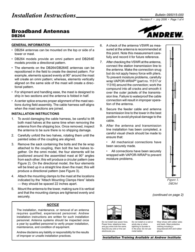
Installation Instructions Bulletin 095015-000 Revision F • July 2006 • Page of 4 Broadband Antennas DB264 GENERAL INFORMATION • DB264 antennas can be mounted on the top or side of a tower or mast. • DB264 models provide an omni pattern and DB264E models provide a directional pattern. • The elements on the DB264/DB264E antennas can be repositioned in the field to create the desired pattern. For example, elements spaced evenly at 90° around the mast will create an omni pattern; whereas, elements vertically aligned on the same side of the mast will create a directional pattern. • For shipment and handling ease, the mast is designed to ship in two sections and the antenna is folded in half. • A center splice ensures proper alignment of the mast sections during field assembly. The cable harness self-aligns when the mast sections are joined. INSTALLATION INSTRUCTIONS 1. To avoid damaging the cable harness, be careful to lift both mast halves at the same time when removing the antenna from the shipping box. Once removed, inspect the antenna to be sure there is no shipping damage. 2. Carefully unfold the two halves, rotating them until the painted sides of the coupling are aligned. 3. Remove the sack containing the bolts and the tie wrap attached to the coupling, then bolt the two halves together. On the omni model, the four elements will be positioned around the assembled mast at 90° angles from each other; this will produce a circular pattern (see Figure 2). On the directional model, the four elements will be lined up in a straight line down the mast; this will produce a directional pattern (see Figure 3). 6. A check of the antenna VSWR as measured at the antenna is recommended at this point. Note this measurement carefully and record it for future reference. 7. After checking the VSWR at the antenna, connect the station transmission line to the antenna. Make the connection snug but do not apply heavy force with pliers. To prevent moisture problems, carefully wrap VAPOR-WRAP® (part no. 11317 or 11316) around the connection; work the compound into all cracks and smooth it over the outer jackets of the transmission line. Failure to waterproof the cable connection will result in improper operation of the antenna. 8. Secure the feeder cable and antenna transmission line to the tower in the best position to avoid physical damage to the cable. 9. After the antenna and transmission line installation has been completed, a careful visual check should be made to ensure that: • All mechanical connections have been securely made. • All connections have been securely wrapped with VAPOR-WRAP to prevent moisture problems. 4. Attach the mounting clamps to the mast at the locations indicated by the “Attach Mounting Clamps Here” labels — they should be spaced 22 inches apart. Figure 1. DB264 5. Mount the antenna to the tower, making sure it is vertical and that the mounting clamps are tightened evenly and securely. (continued on page 2) NOTICE The installation, maintenance, or removal of an antenna requires qualified, experienced personnel. Andrew installation instructions are written for such installation personnel. Antenna systems should be inspected once a year by qualified personnel to verify proper installation, maintenance, and condition of equipment. Andrew disclaims any liability or responsibility for the results of improper or unsafe installation practices. Do not install near power lines. Power lines, telephone lines, and guy wires look the same. Assume any wire or line can electrocute you. Do not install on a wet or windy day or when lightning or thunder is in the area. Do not use metal ladder. Wear shoes with rubber soles and heels. Wear protective clothing including a long-sleeved shirt and rubber gloves. Installation Training Available at Andrew Institute DB264 Broadband Antennas Continued from page 1 Andrew Corporation Bulletin 095015-000 • Revision F • July 2006 • Page of 4 CHANGING THE RADIATION PATTERN As stated above, the DB264 has all elements positioned evenly, every 90°, around the mast for an omni pattern while the DB264E has all elements aligned in a straight line on the same side of the mast for a directional pattern. If desired, the omni model can be field adjusted to achieve a directional pattern and the directional model can be field adjusted to achieve an omni pattern. Changing an Omni Pattern to a Directional Pattern 1. If the antenna is currently mounted to a tower, remove it from the tower and place it onto four supports as shown in Figure 2a. The supports should be tall enough to allow the elements to clear the ground. 2. Loosen the bolts that hold the topmost element to the mast and rotate the element 45° toward the second element (see Figure 2b). 3. Loosen the second element and rotate it 45° so the two elements are aligned. Be careful not to rotate any of the elements more than 45° to avoid placing undue strain on the wiring harnesses (see Figure 2b). 4. Once the two upper elements are aligned, tighten the bolts that clamp the elements to the mast. 5. Remove the four flange bolts from the center flanges of the mast. Caution: Be sure both halves of the mast are supported as shown in Figures 2a through 2c before removing the bolts from the center flanges. Also, remember that the transmission line runs inside the mast. Do not allow the mast sections to separate so much that it causes damage to the transmission line. 6. Rotate the upper half of the mast 180° until the two top elements point in a direction that is 45° between the two bottom elements (see Figure 2c). Caution: Remember, the transmission line runs through the mast. Do not allow the mast sections to separate so much that it causes damage to the transmission line. 7. Position the mast sections together. Reinstall the flange bolts that hold the sections together and tighten the flange bolts. 8. Loosen the bolts that clamp the two bottom elements to the mast and rotate each one 45° so they line up with the top elements (see Figure 2c). 9. Once the elements are aligned, tighten the bolts that clamp the elements to the mast. 10. Mount the antenna to the tower. Position it so the elements point in the direction of maximum desired coverage. Figure 2a Figure 2b Figure 2c Figures 2a through 2c. Changing an Omni Pattern (DB264) to a Directional Pattern (DB264E) Andrew Corporation Continued from page 2 DB264 Broadband Antennas Bulletin 095015-000 • Revision F • July 2006 • Page of 4 Changing a Directional Pattern to an Omni Pattern 1. If the antenna is currently mounted to a tower, remove it from the tower and place it onto four supports as shown in Figure 3a. The supports should be tall enough to allow the elements to clear the ground. 2. Remove the four bolts from the center flanges of the mast. Caution: Be sure both halves of the mast are supported as shown in Figures 3a through 3c before removing the bolts from the center flanges. Also, remember that the transmission line runs inside the mast. Do not allow the mast sections to separate so much that it causes damage to the transmission line. 3. Rotate the upper half of the mast 180° so the two bottom elements and the two top elements point in opposite directions (see Figure 3b). 4. Position the mast sections together. Reinstall the flange bolts that hold the sections together and tighten the flange bolts. 10. Looking from the bottom of the mast toward the top, rotate the second element 45° counterclockwise, to the left (see Figure 3c). 11. By sighting past the edges of a square, check to see that the two bottom elements are now 90° apart. Tighten the bolts that clamp the elements to the mast. 12. Loosen the bolts that clamp the third element to the mast and rotate it 45° to the right until it is pointed in the direction opposite the bottom element (see Figure 3c). 13. Loosen the bolts for the top element and rotate it 45° to the left so that it points in a direction opposite the second element (see Figure 3c). 14. Once the elements are aligned, tighten the bolts that clamp the elements to the mast. 15. Mount the antenna to the tower. Be sure to position it so the bottom element points away from the tower. 8. Loosen the bolts that clamp the two bottom elements to the mast. 9. Looking from the bottom of the mast toward the top, rotate the bottom element 45° clockwise, to the right (see Figure 3c). Figure 3a Figure 3b Figure 3c Figures 3a through 3c. Changing a Directional Pattern (DB264E) to an Omni Pattern (DB264) DB264 Broadband Antennas Continued from page 3 Andrew Corporation Bulletin 095015-000 • Revision F • July 2006 • Page of 4 SIDE MOUNTING The normal horizontal radiation pattern of an antenna becomes distorted when the antenna is mounted on the side of a tower. However, this distortion can often be used to an advantage if the distorted pattern shape is known. The patterns shown in Figures 4a thru 4c indicate the approximate pattern shapes of DB264 and DB264E antennas when side mounted on a tower that has an 18-24 inch face, using the DB5001 side mount kit. The 0° direction is from the center of the tower through the antenna mast. Figure 4a. DB264E (Directional) Elements Pointed Away From The Tower Figure 4b. DB264 (Omni) Mounted On The Side Of A Tower Figure 4c. DB264E (Directional) Elements Pointed Toward The Tower Andrew Corporation Base Station Antennas Telephone: 1-800-676-5342 2601 Telecom Parkway FAX (U.S.A.): 214-688-0089 Richardson, TX U.S.A. 75082 Internet: www.andrew.com Customer Service, 24 Hour: U.S.A. • Canada • Mexico: 1-800-255-1479 Printed in U.S.A. U.K.: 0800 250055 Copyright © 2006 by Andrew Corporation Other Europe: +44 1592 782612
