Application Note
Solving Intermittent Transport Stream
Problems with CaptureVu Technology
TM
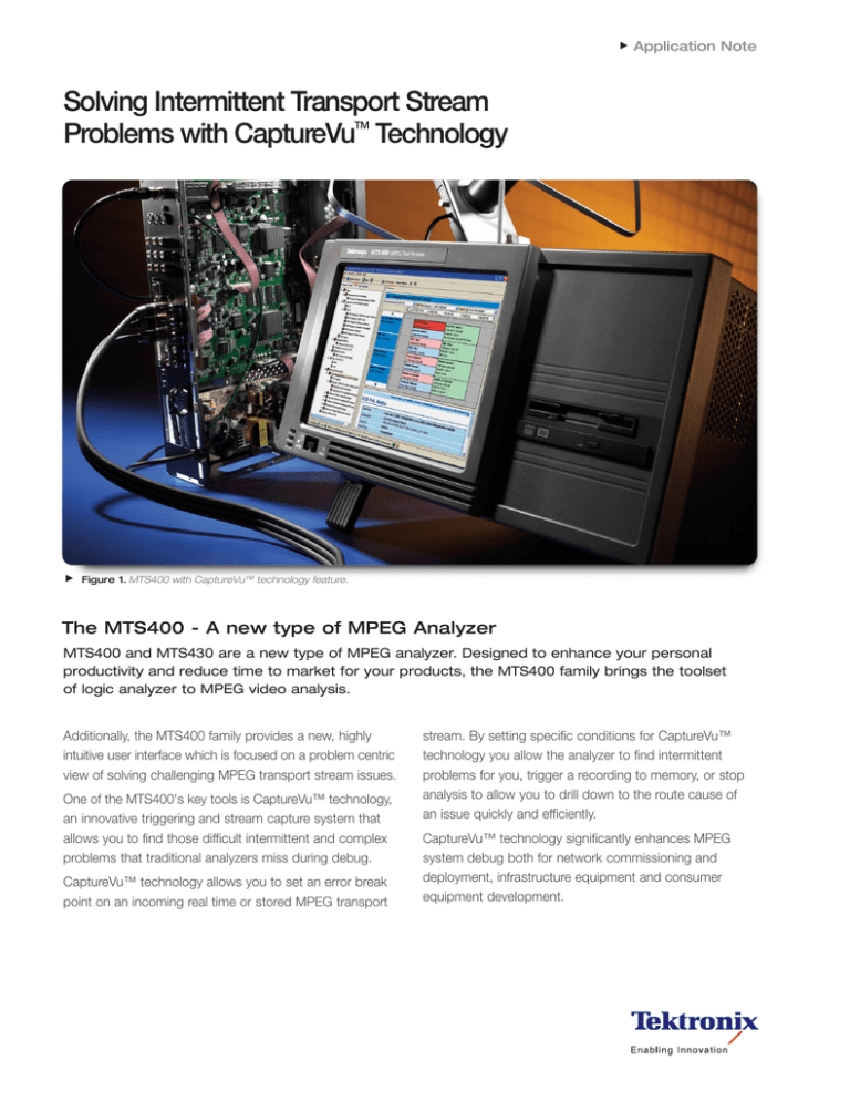
Figure 1. MTS400 with CaptureVu™ technology feature.
The MTS400 - A new type of MPEG Analyzer
MTS400 and MTS430 are a new type of MPEG analyzer. Designed to enhance your personal
productivity and reduce time to market for your products, the MTS400 family brings the toolset
of logic analyzer to MPEG video analysis.
Additionally, the MTS400 family provides a new, highly
intuitive user interface which is focused on a problem centric
view of solving challenging MPEG transport stream issues.
One of the MTS400's key tools is CaptureVu™ technology,
an innovative triggering and stream capture system that
allows you to find those difficult intermittent and complex
problems that traditional analyzers miss during debug.
CaptureVu™ technology allows you to set an error break
point on an incoming real time or stored MPEG transport
stream. By setting specific conditions for CaptureVu™
technology you allow the analyzer to find intermittent
problems for you, trigger a recording to memory, or stop
analysis to allow you to drill down to the route cause of
an issue quickly and efficiently.
CaptureVu™ technology significantly enhances MPEG
system debug both for network commissioning and
deployment, infrastructure equipment and consumer
equipment development.
Solving Intermittent Transport Stream Problems with CaptureVu™ Technology
Application Note
Figure 2. Selecting a CaptureVu™ technology feature Breakpoint.
Figure 3. CaptureVu™ technology feature Breakpoint set on
TR 101 290 2.3a PCR Repetition.
CaptureVu™ technology - An Overview
CaptureVu™ technology allows you to set, capture and
analyze MPEG Transport Stream events during both
deferred and real-time analysis. This includes real time
CaptureVu™ technology analysis of live IP streams carrying
MPEG data arriving at the analyzer's Ethernet port.
To use CaptureVu™ technology you set a break point trigger on any of the MPEG measurement parameters that the
MTS400 can make. When a test flagged with CaptureVu™
technology executes and fails the analyzer stops at the
transport packet containing the errored data.
In real time mode the analyzer stores a record of the
200 MByte of transport stream prior to the CaptureVu™
technology trigger point.
Trigger options for CaptureVu™ technology include:
ETSI TR 101 290 1st, 2nd, 3rd priority tests
Multiplex occupancy outside of user defined limits
Tests including: SFN, ISDB, ATSC PSIP, and PCR OJ,
FO, and DR.
Links to the test and the packet at the point at which
the test failed are available in the CaptureVu™ technology
Settings dialog box.
2
www.tektronix.com/video
Setting Up CaptureVu™ Technology
CaptureVu™ technology is activated when a test flagged
with a CaptureVu™ technology breakpoint falls outside
the parameters set for the test. Breakpoints can be set at
any time. In real time mode CaptureVu™ technology will
activate as soon as the flagged test fails.
You can set a CaptureVu™ technology breakpoint as
follows: In either the Program or Tests view, locate and
highlight the test required. From the right-click menu,
select CaptureVu™ technology Breakpoint (Figure 2).
Note the addition of the CaptureVu™ technology icon
beside the test entry (Figure 3).
The CaptureVu™ technology breakpoint is now set. You
can set as many breakpoints as you require, tests being
performed have their failure triggered via a logical OR of all
results. When an error is next detected on any breakpoint
test, analysis (real-time or deferred) will be stopped and the
test identified.
Solving Intermittent Transport Stream Problems with CaptureVu™ Technology
Application Note
Figure 4. CaptureVu™ technology Breakpoint activation dialog.
Figure 5. CaptureVu™ technology feature Breakpoint - test view.
CaptureVu™ Technology Analysis
The CaptureVu™ technology breakpoint will operate
during real-time and deferred analysis. The CaptureVu™
technology Settings dialog box is displayed as soon as
a breakpoint is activated (Figure 4).
In real time CaptureVu™ technology the displayed dialog
box contains the following fields:
When enabled, the CaptureVu™ technology setting dialog
box is opened automatically when a breakpoint occurs.
The CaptureVu™ technology Settings dialog box can
also be viewed at any time by selecting the CaptureVu™
technology Settings button on the tool bar.
This dialog box displays the transport packet in which
the test has failed
This dialog box displays the test at which the test
has failed
Clicking either the “triggered by” or the “At packet” link will
open the related view (Tests or Packets) and highlight the
relevant test or packet (Figure 5).
www.tektronix.com/video
3
Solving Intermittent Transport Stream Problems with CaptureVu™ Technology
Application Note
Figure 6. MTS400 family test view.
Figure 7. Selecting CaptureVu™ technology feature trigger on test
3.5a SDT Actual.
How CaptureVu™ Technology solves your stream problems
The following example shows how to use CaptureVu™
technology to solve real world problems with a pre captured
complex transport stream, and how to drill down to get
graphical confirmation of the transport stream error.
To do this we set a CaptureVu™ technology break point
on a TR 101 290 error defined by the DVB Measurement
Guidelines for a Service Description Table Actual error (SDT
Actual). This test defined in TR 101 290 as test 3.5a checks
that the SDT information which describes the services
contained in a particular Transport Stream is transmitted
at least every 2 seconds on PID 0x0011.
The following shows how to trap a suspected infringement
of SDT repetition rate which could cause a set top box
operational issues.
Firstly clicking on the Test tab of the analyzer produces a
list of all tests undertaken, clicking on TR 101 290 takes
you down a layer to the explicit priority 1, 2 and 3 test,
with SDT actual residing under priority 3 test (Figure 6).
4
www.tektronix.com/video
By right clicking on the test 3.5a SDT Actual, a dialog
appears which allows you to select CaptureVu™ technology
by clicking on the
CaptureVu™ technology icon
(Figure 7).
Solving Intermittent Transport Stream Problems with CaptureVu™ Technology
Application Note
Figure 8. CaptureVu™ technology feature set on test 3.5a SDT Actual.
Figure 9. Resuming Analysis.
When selected, the
CaptureVu™ technology icon
appears against the selected test (Figure 8).
Figure 10. Real-time CaptureVu™ technology feature of 3.5a test
SDT Actual.
The analysis can now be restarted to find the next occurrence
of a SDT Actual timing infringement (Figure 9).
When the analyzer detects the next SDT Actual error
condition is pauses analysis and captures the fault showing
the fault and packet number where it occurred (Figure 10).
www.tektronix.com/video
5
Solving Intermittent Transport Stream Problems with CaptureVu™ Technology
Application Note
Figure 12. SI/PSI Analysis selection.
Clicking on the SI/PSI Tab (Figure 12) of the analyzer allows
the SDT Actual timing graphs to be displayed showing the
timing infringement where the table repetition rate has
exceded the 2,000mS limit (Figure 13).
6
www.tektronix.com/video
Figure 13. SDT Actual timing graph with limits mask shown.
Clicking on the Restart Analysis button will allow the next
SDT Actual error to be quickly found, quantified and logged.
Solving Intermittent Transport Stream Problems with CaptureVu™ Technology
Application Note
Conclusion
In conclusion, CaptureVu™ technology provides the ideal tool
for rapidly finding and isolating difficult intermittent problems
in Transport Streams, both in real time and deferred time,
saving you time, money and improving customer satisfaction.
www.tektronix.com/video
7
Contact Tektronix:
ASEAN / Australasia / Pakistan (65) 6356 3900
Austria +41 52 675 3777
Balkan, Israel, South Africa and other ISE Countries +41 52 675 3777
Belgium 07 81 60166
Brazil & South America 55 (11) 3741-8360
Canada 1 (800) 661-5625
Central East Europe, Ukraine and Baltics +41 52 675 3777
Central Europe & Greece +41 52 675 3777
Denmark 80 88 1401
Finland +41 52 675 3777
France & North Africa +33 (0) 1 69 81 81
Germany +49 (221) 94 77 400
Hong Kong (852) 2585-6688
India (91) 80-22275577
Italy +39 (02) 25086 1
Japan 81 (3) 6714-3010
Luxembourg +44 (0) 1344 392400
Mexico, Central America & Caribbean 52 (55) 56666-333
Middle East, Asia and North Africa +41 52 675 3777
The Netherlands 090 02 021797
Norway 800 16098
People’s Republic of China 86 (10) 6235 1230
Poland +41 52 675 3777
Portugal 80 08 12370
Republic of Korea 82 (2) 528-5299
Russia, CIS & The Baltics 7 095 775 1064
South Africa +27 11 254 8360
Spain (+34) 901 988 054
Sweden 020 08 80371
Switzerland +41 52 675 3777
Taiwan 886 (2) 2722-9622
United Kingdom & Eire +44 (0) 1344 392400
USA 1 (800) 426-2200
USA (Export Sales) 1 (503) 627-1916
For other areas contact Tektronix, Inc. at: 1 (503) 627-7111
Updated 10 February 2005
For Further Information
Tektronix maintains a comprehensive, constantly expanding collection of
application notes, technical briefs and other resources to help engineers
working on the cutting edge of technology. Please visit www.tektronix.com
Copyright © 2005, Tektronix, Inc. All rights reserved. Tektronix products are covered by U.S. and foreign
patents, issued and pending. Information in this publication supersedes that in all previously
published material. Specification and price change privileges reserved. TEKTRONIX and TEK are
registered trademarks of Tektronix, Inc. All other trade names referenced are the service marks,
trademarks or registered trademarks of their respective companies.
03/05 EA/WOW
2AW-18728-0


