Rotating Electrical Machines
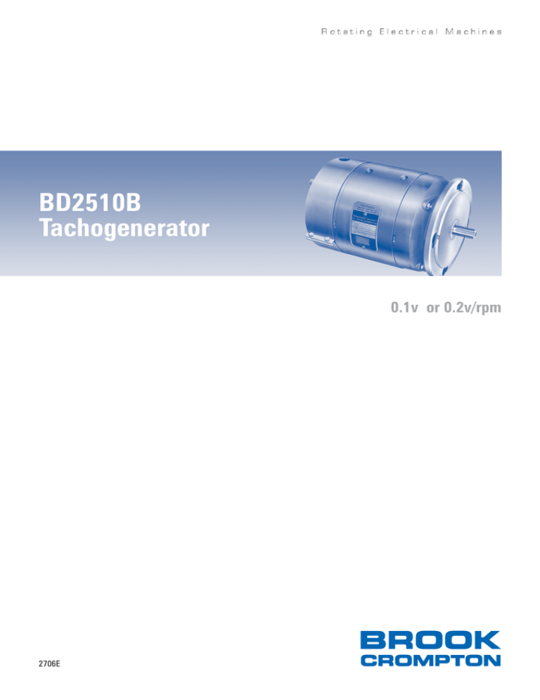
BD2510B
Tachogenerator
0.1v or 0.2v/rpm
2706E
2706E Issue 1e
BD2510B Tachogenerator
Introduction
The BD2510B Tachogenerator is famous for its robust construction and for its high accuracy
and consistent voltage proportional to speed. Brook Crompton (previously GEC) have been
continuously manufacturing the same design of tachogenerator for over 40 years, taking care
to preserve the special materials and design features which provide its unique performance.
With this wealth of experience and knowledge applied, our tachogenerators are renowned
throughout the world.
Specification for standard tachogenerator
Volts per 1000 r/min
Speed range
Maximum Emergency Overspeed
Armature Resistance at 20ºC
Armature Inductance
Drive torque at 1500 r/min with minimum load impedance
Direction of Rotation
Maximum Output
Maximum load impedance
Maximum temperature rise
Insulation class
Maximum ambient temperature
High voltage test
Insulation resistance (as tested)
Armature moment of Inertia (mr2)
Frame
Degree of protection and cooling form
Brushes and brush dimensions
Brush grade
Commutator
Armature
Field Magnets
Bearings
Connections
Approximate overall dimensions
Total weight (flange mounted)
BD2510B/1
100 ±5%
0-4000 r/min
5000 r/min
25 ±10% ohms
0.218 Henries
0.197Nm
(28 oz/in)
BD2510B/2
200 ±5%
0-2000 r/min
2500 r/min
65 ±10% ohms
0.566 Henries
0.266Nm
(32 oz/in)
See Note
1
BD2510B/1 and BD2510B/2
Reversible
0.1A at 400V
4000 ohms
40K
Class B
65ºC (MG-18-632)
2000V, 50Hz for one minute
Exceeding 100 megohms
0.0021 kg m2 (7.2lb in2)
Rolled steel
IP44 and IC0041 6
2 per arm 3/8” wide x 1/4” thick x 1” long
Silver graphite 0.1A
Monel metal, 54 segments
18 slots, skewed
Alcomax 4
Pre-loaded ball bearings
Brought to terminal box
Ø165mm (6.5”) x 291mm (11 15/32”) long
12.8 kg (28.25 lb)
2
3
4
4
4
Notes
1. The actual output voltage for any individual tachogenerator lies between 95% and 105% of the nominal rated value. The
performance figures appearing in the table (page *) are then applicable to the individual voltage.
2. Overspeeds are likely to cause bad commutation which may temporarily affect the characteristics of the tachogenerator.
3. These tachogenerators are supplied for reversible rotation only.
4. Class B insulation is used throughout although temperature rise in normal operation is well within the normal Class A limits. This
ensures extended life expectation and alternatively allows operation in ambients up to 80ºC without harmful effects to the machine..
Standard features and alternatives
Voltage
Maximum output
Mounting
Cable entry
Standard
IP44
IC0041
Standard at drive end
Stub shaft at non-drive end
CM20
Rotation
Reversible
Ripple
Degree of protection
Cooling form
Shaft extension
2
Standard Features
Alternatives
100V, 200V per 1000 r/min
None
0.1A at 400V
Flange as standard dimension sheet B56 flange to BS2048
NEMA ‘C’ flange
Detachable feet
Reduced ripple
Special at drive end
Special at both ends
1/2” Briggs
PG11
None
NEMA Specification MG1-18, 626-940, ‘DC permanent tachometer
generators for control systems’
The BD2510B tachogenerator complies with the test and performance
requirements of this specification with the added advantage of an
insulation system superior to that specified. The manufacturing
requirements of this specification may also be satisfied if requested at the
time of ordering.
2706E Issue 1e
BD2510B Tachogenerator
Applications and Performance data
Applications
Standard Reversible Tachogenerator Performance
high accuracy digital voltmeter at rated load
Applications exist for the tachogenerator wherever
Figures at 1500 r/min
Note: the inherent a.c ripple in output voltage of a
a d.c. voltage proportional to speed is required. It
Maximum deviation from linearity
±0.2%
d.c generator has two main, components.
provides a highly accurate and consistent feed-back
Maximum reversing error
±0.2%
(1) low frequency variation which occurs at 1
voltage suitable for feeding high impedance
Maximum voltage regulation
0.9%
and 2 cycles per revolution and is minimised in
electronic circuit, it may also be used for supplying
Maximum ripple voltage
0.5%
the B2510B tachogenerator by careful
instruments and for other loads where greater
Maximum amb. temp. factor
weights are required, but where the same degree
Maximum short term instability
of accuracy is not essential.
Maximum long term instability
An indication of some applications are controlling
These derivation of these figures is defined in IEEE
Specification No. 251 and summarised as follows:
designed drive arrangements, as mentioned
paper mill/steel mill drives, controlling the heat
treatment of steel rods used in reinforced concrete
Deviation from linearity
(2) High frequency variation, caused by the
and in colliery equipment.
The tachogenerator is connected to a non-inductive
armature slots, occurring at 18 cycles per
resistance to give rated output and at least seven
revolution. To minimised this the armature slots are
Performance data
voltage readings are taken, evenly spaced
skewed and the stator poles specially shaped and
A testing programme to determine the
throughout the rated speed range. An average volts
offset circumferentially.
characteristics and accuracy of the BD2510B
per 1000 r/min is obtained by dividing the sum of
Ambient temperature factor
tachogenerator was undertaken by the University of
the output voltages by the sum of the
the tachogenerator is run in a temperature
Aston in Birmingham, England, whose laboratories
corresponding speeds in thousands of r/min. At any
controlled enclosure. Voltage output readings at
have established reputation for independent
speed the difference between the voltage per 1000
rated load are taken at temperatures approximately
investigations.
r/min output at that speed and the average,
25°C apart and the difference between them
Tachogenerators taken at random from stock were
expressed as a percentage of the average, is
expressed as the percentage change per degree
tested by University staff using IEE Specification No.
defined as the deviation from linearity
Centigrade from the reading at the lower
251 ‘Proposed test procedure for direct current
The procedure is repeated at no-load and also in
temperature to that at the higher temperature. The
tachometer generators’ as a guide. The figures
reverse rotation.
procedure is repeated for another pair of
shown in the table were derived from these tests
Reversing error
temperatures in a different part of the specified
according to the specification in collaboration with
Using the same arrangement as for linearity, voltage
ambient range.
the University. The certified accuracy of the
output readings are token in both rotations after a
Note: Temperature effects are reduced to a
apparatus used enabled the University to offer the
series of reversals. The reversing error is the
minimum in the BD2510B tachogenerator by the
following limits of accuracy in their readings at 1500
difference between the output voltage in each
use of temperature compensating magnetic shunts
r/min.
rotation, expressed as a percentage of the average
attached to the stator pole pieces.
±0.003% V per C
0.03%
0.02%V per hour
component design coupled with accuracy in
machining and assembly. This ripple can
however, be adversely affected by poorly
under ‘Installation'
Speed measurement
±0.0021%
of those two voltages.
Short term instability
Voltage measurement
±0.0165%
Voltage regulation
The tachogenerator is run at rated load for 3 hours
mV per r/min calculated from above ±0.0186%
This is not normally of very great importance in a
to allow conditions to stabilise and then continued
ie performance figures are derived from readings
tachogenerator, which usually has a load of
for a further 5 hours during which the-largest peak-
whose accuracy is certified better than ±2 in 104 or
constant impedance. It is calculated from the
to-peak voltage variation in any one hour is
±0.02mV per r/min or ±200 parts per million.
linearity readings as the difference between the no-
recorded. This variation is expressed as a
load and rated load average volts per 1000 r/min
percentage of the average voltage over that hour.
expressed as a percentage of the rated load value.
Long term instability
Ripple voltage
Continuing the above run over 24 hours, hourly
The total ripple is measured by a direct reading
readings are taken and the maximum percentage
valve voltmeter and the rms value expressed as a
change in voltage per hour is recorded.
percentage of the d c. output voltage as read on a
Installation and maintenance
A separate document is available detailing the
safety measures that must be observed when
installing the machine and maintenance
considerations for machines that are in operation.
It is important that electrical installation is
conducted in accordance with relevant local
regulations and that bearing replacement, when
necessary, is achieved without removing the
armature (to maintain accurate performance of the
tachogenerator). Machines may be returned to the
factory for servicing and remagnetisation.
see back page for a BD2510 outline dimensions
3
Rotating Electrical Machines
BD2510 Tachogenerator Dimensions
Note:
Can also be supplied with dimensions which
conform to NEMA standards, details available
on request.
Every care has been taken to ensure the accuracy of the information
contained in this publication, but, due to a policy of continuous
development and improvement the right is reserved to supply products
which may differ slightly from those illustrated and described in this
publication
For the most recent version of any Brook Crompton catalogue/leaflet,
please refer to www.brookcrompton.com
Brook Crompton Special Products
Unit 1, Excelsior Industrial Estate
Cakemore Road, Rowley Regis
West Midlands B65 0QT. UK
Tel:
+44 (0) 121 6983100
Fax:
+44 (0) 121 6983160
E-mail: refer to website
Internet: www.brookcrompton.com/specialproducts.htm
dh0704/11/07 2706E issue 1e
© Copyright 2007. Brook Crompton. All rights reserved.


