MED10130102
09/2015
Instruction Bulletin
ENGLISH
Replaces MED10130101, 01/2013
Upgrading Legacy Iso-Gard™ Line Isolation Monitors and
Remote Indicators
Retain for future use.
Introduction
This bulletin describes the procedures and components necessary to
replace a Square D™ brand, Iso-Gard™ line isolation monitor (LIM) with an
Iso-Gard Series 6 LIM manufactured by Schneider Electric. It also details
the components required to connect legacy remote indicators to the
Iso-Gard Series 6 LIM.
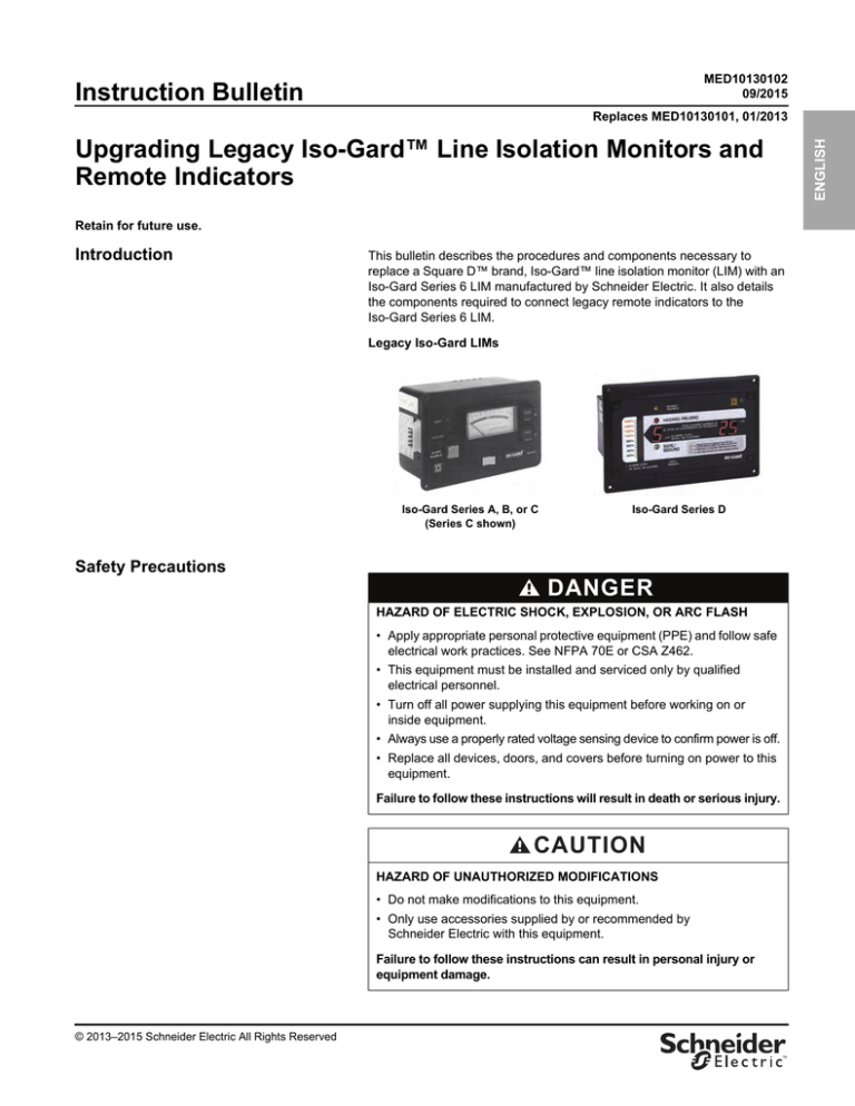
Legacy Iso-Gard LIMs
Iso-Gard Series A, B, or C
(Series C shown)
Iso-Gard Series D
Safety Precautions
DANGER
HAZARD OF ELECTRIC SHOCK, EXPLOSION, OR ARC FLASH
• Apply appropriate personal protective equipment (PPE) and follow safe
electrical work practices. See NFPA 70E or CSA Z462.
• This equipment must be installed and serviced only by qualified
electrical personnel.
• Turn off all power supplying this equipment before working on or
inside equipment.
• Always use a properly rated voltage sensing device to confirm power is off.
• Replace all devices, doors, and covers before turning on power to this
equipment.
Failure to follow these instructions will result in death or serious injury.
CAUTION
HAZARD OF UNAUTHORIZED MODIFICATIONS
• Do not make modifications to this equipment.
• Only use accessories supplied by or recommended by
Schneider Electric with this equipment.
Failure to follow these instructions can result in personal injury or
equipment damage.
© 2013–2015 Schneider Electric All Rights Reserved
™
Upgrading Legacy Iso-Gard™ Line Isolation Monitors and Remote Indicators
Replacing the LIM
MED10130102
09/2015
ENGLISH
Replacing the LIM
Use the following instructions to replace an Iso-Gard Series A, B, C, or D
LIM with an Iso-Gard Series 6 LIM.
Removing a Series A, B, C, or D LIM
1. Review and follow the safety precautions on page 1.
2. Turn off all power supplying this equipment.
3. Unplug the connector from the LIM.
4. Remove the #8-32 hex nuts securing the LIM mounting bracket to the
backplate, and remove the LIM and bracket as an assembly. Retain the
hex nuts.
5. Disconnect all wires connected to connector plate and label them
(L1, L2, ground(s), and remote accessory).
6. Remove the #8-32 hex nuts securing the LIM connector plate to the
backplate and remove the connector plate. Retain the hex nuts.
Series A, B, or C
3
4
5
6
Series D
4
3
5
6
2
© 2013–2015 Schneider Electric All Rights Reserved
Installing a Series 6 LIM Using the
LIM Bracket
Upgrading Legacy Iso-Gard™ Line Isolation Monitors and Remote Indicators
Replacing the LIM
NOTE: The torque range for all mounting hardware is 2.8–3.5 lb-in
(0.32-0.40 N•m).
ENGLISH
MED10130102
09/2015
1. Review and follow the safety precautions on page 1.
2. Turn off all power supplying this equipment.
3. Set the LIM mounting bracket to the correct height (page 4).
4. Attach the Series 6 LIM to the mounting bracket using the provided
#4-40 x 0.5 in. hardware.
5. Attach the LIM assembly to the backplate using the retained #8-32 hex
nuts.
6. Attach the LIM terminal connector to the backplate using the retained
#8-32 hex nuts.
7. Drill and tap two #6-32 holes as required for mounting the auxiliary
transformer (4800XMIA); order separately when remote accessories are
connected to panel. Collect and remove all metal shavings.
8. Make connections from auxiliary transformer to the 4800IG6C connector
plate.
9. Detach the wire marked 12VDC Com from the 15-pin wiring harness.
Insulate the uninsulated wire end using shrink tubing and secure it to the
harness with a wire tie.
10. Plug in the wiring harnesses from the connector plate to the LIM.
NOTE: For proper functionality, both relay settings must remain at the
factory setting (N/C-T Mode). See the SETTING/RELAY menu in instruction
bulletin MED101101xx, Iso-Gard™ Line Isolation Monitor.
4
5
7
8
9
6
10
© 2013–2015 Schneider Electric All Rights Reserved
3
Upgrading Legacy Iso-Gard™ Line Isolation Monitors and Remote Indicators
Replacing the LIM
Adjusting the Variable-Height Mounting Bracket
MED10130102
09/2015
The mounting bracket for the Iso-Gard Series 6 LIM (catalog number
4800IG6BKTVM) can be set to four different heights.
ENGLISH
(4) #6-32 x 0.25 in.
pan head screws
5.125
(130)
3.75
(95)
3.25
(83)
3.0
(76)
Dimensions in Inches
(mm)
4
© 2013–2015 Schneider Electric All Rights Reserved
Upgrading Legacy Iso-Gard™ Line Isolation Monitors and Remote Indicators
Replacing the LIM
Installing a Series 6 LIM Without Using
the LIM Bracket
Use this procedure for all installations where the interior-to-trim distance is
other than the heights shown on page 4. This procedure can also be used
as an optional mounting procedure in existing medical panels.
ENGLISH
MED10130102
09/2015
NOTE: Special brackets are available on request; delivery time is 4–6
weeks.
NOTE: The torque range for all mounting hardware is 2.8–3.5 lb-in
(0.32-0.40 N•m).
1. Review and follow the safety precautions on page 1.
2. Turn off all power supplying this equipment.
3. Drill four 0.156 in. (4 mm) diameter holes in the dead front panel. Collect
and remove all metal shavings.
4. Attach the LIM to the dead front panel using the four #4-40 screws and
hex nuts provided with the LIM.
5. Attach the LIM terminal connector to the backplate using the two #8
self-tapping screws provided with the LIM.
6. Drill and tap two #6-32 holes as required for mounting the auxiliary
transformer (4800XMIA); order separately when remote accessories are
connected to panel. Collect and remove all metal shavings.
7. Make connections from auxiliary transformer to the connector plate.
8. Detach the wire marked 12VDC Com from the 15-pin wiring harness.
Insulate the uninsulated wire end using shrink tubing and secure it to the
harness with a wire tie.
9. Plug in the wiring harnesses from the connector plate to the LIM.
NOTE: For proper functionality, both relay settings must remain at the
factory setting (N/C-T Mode). See the SETTING/RELAY menu in instruction
bulletin MED101101xx, Iso-Gard™ Line Isolation Monitor.
6.50
3.25
(83)
(165)
CL
2.00
(51)
Existing LIM opening
4.00
CL
(102)
3
Dead front panel
Dimensions in Inches
4
6
(mm)
7
8
5
9
© 2013–2015 Schneider Electric All Rights Reserved
5
Upgrading Legacy Iso-Gard™ Line Isolation Monitors and Remote Indicators
Connecting Legacy Remote Indicators
ENGLISH
Connecting Legacy Remote
Indicators
MED10130102
09/2015
When a legacy Iso-Gard LIM is upgraded to a Series 6 LIM, additional
components may be needed to connect existing remote indicators. Each
component can be ordered separately or as part of a kit. See Schneider
Electric catalog #8501CT1301 for ordering details.
Component
Catalog
Number
Series 6 LIM
IG6M
Connector plate and cables
4800IG6C
Variable-height
mounting bracket
4800IG6BKTVM
Transformer
4800XMIA
Connector box and
wiring harness
4800RA1WMAHA
NOTE: Wiring diagrams for connecting remote indicators to the Iso-Gard
Series 6 LIM are shown on pages 13 and 14.
6
© 2013–2015 Schneider Electric All Rights Reserved
Upgrading Legacy Iso-Gard™ Line Isolation Monitors and Remote Indicators
Connecting Legacy Remote Indicators
If you have one of these
remote indicators
ORICA
IA1C
RA1 PM (panel-mounted)
RA1 WM (wall-mounted)
© 2013–2015 Schneider Electric All Rights Reserved
You’ll need to add
these components
ENGLISH
MED10130102
09/2015
IG6M
4800IG6BKTVM
4800IG6C
4800XMIA
IG6M
4800IG6C
4800IG6BKTVM
4800RA1WMAHA
7
Upgrading Legacy Iso-Gard™ Line Isolation Monitors and Remote Indicators
Connecting Legacy Remote Indicators
MED10130102
09/2015
ENGLISH
If you have one of these
remote indicators and your application
requires an ammeter per the NEC a
You’ll need to replace the remote
indicator with one of these
ORICA5C
IG2000CBMPM (panel-mounted)
M5IAI
IG2000CBMST0614
(designed for mounting in a
legacy back box–530087BB)
4800IG6C
M5IAI50
IG2000CBMG4
(designed for mounting in a
four-gang electrical box)
4800IG6BKTVM
Plus, add the IG6KIT upgrade kit, which
contains these components b
IG6M
a NEC Section 517.160(B)(1)(3)
Exception: The line isolation monitor shall be permitted to be a composite unit, with sensing section cabled to a separate display panel section on which the alarm
or test functions are located.
Information Note: It is desirable to locate the ammeter so that it is conspicuously visible to person(s) in the anesthetizing location.
b These components can be ordered separately or as a kit (catalog number IG6KIT).
8
© 2013–2015 Schneider Electric All Rights Reserved
Upgrading Legacy Iso-Gard™ Line Isolation Monitors and Remote Indicators
Connecting Legacy Remote Indicators
If you have this remote indicator
and your application does not require an
ammeter per the NEC a
You’ll need to replace the remote indicator with this one b
ORICA5C
IG2000PPM
(includes IG2000P and panel-mount bracket)
M5IAI
IG2000PST0614
M5IAI50
IG2000PG4
(designed for mounting in a
four-gang electrical box)
ENGLISH
MED10130102
09/2015
a NEC Section 517.160(B)(1)(3)
Exception: The line isolation monitor shall be permitted to be a composite unit, with sensing section cabled to a separate display panel section on which the alarm
or test functions are located.
Information Note: It is desirable to locate the ammeter so that it is conspicuously visible to person(s) in the anesthetizing location.
b These remote indicators can be connected directly to the Iso-Gard Series 6 LIM. See the instructions included with the device.
© 2013–2015 Schneider Electric All Rights Reserved
9
Upgrading Legacy Iso-Gard™ Line Isolation Monitors and Remote Indicators
Connecting Legacy Remote Indicators
Installing a 4800RA1WMA Converter Box
MED10130102
09/2015
Use the 4800RA1WMA converter box to connect an Iso-Gard Series 6 LIM
to an RA1 panel- or wall-mounted remote indicator.
ENGLISH
WARNING
HAZARD OF EQUIPMENT SHUTDOWN
To prevent an inadvertent shutdown of the Iso-Gard Series 6 LIM, do not
energize more than four RA1 remote indicators simultaneously with the
RA1WMA converter box.
Failure to follow these instructions can result in death or serious injury.
Mounting
Mount the converter box in a suitable location using the four screws provided.
Adding a Voltage Jumper
1. Review and follow the safety precautions on page 1.
2. Turn off all power supplying this equipment.
3. Remove and retain the four screws securing the cover to the converter box.
4. Remove the cover and locate a four-pin, female connector labeled “JP1.”
JP1
120 V jumper
5. If the system voltage is 120 V, connect the voltage jumper labeled “120.”
or
If the system voltage is 208 V, connect the voltage jumper labeled “208.”
6. Replace the cover and secure with the four screws removed in step 1.
10
© 2013–2015 Schneider Electric All Rights Reserved
Connecting to an Iso-Gard 4800IG6C
Connector Plate
Upgrading Legacy Iso-Gard™ Line Isolation Monitors and Remote Indicators
Connecting Legacy Remote Indicators
The connector plate for an Iso-Gard Series 6 LIM is connected to the
RA1WMA converter box with the RA1HA wiring harness, sold separately.
ENGLISH
MED10130102
09/2015
4800IG6C Connector Plate
1. Remove the converter box cover.
2. Connect the 1 x 15-pin female connector from the RA1HA wiring
harness to the 1 x 15-pin male plug inside the converter box.
3. Route the wiring for the female connector through the slot on the
converter box.
4. Replace the converter box cover.
RA1WMA
convertor box
RA1HA wiring
harness
To 4800IG6C
connector plate
© 2013–2015 Schneider Electric All Rights Reserved
11
Upgrading Legacy Iso-Gard™ Line Isolation Monitors and Remote Indicators
Connecting Legacy Remote Indicators
MED10130102
09/2015
Connecting Other Devices
ENGLISH
Annunciator Panels (Nurse Stations)
These devices can be fed from multiple LIMs. For each LIM replaced,
connect according to the wiring diagrams on pages 13 and 14.
IA4CI
Power Modules
IA8CI
To connect these devices, refer to the wiring diagrams on pages 13 and 14.
XRIAI
Supervisory Stations
To connect these devices, refer to the wiring diagrams on pages 13 and 14.
8CIIAI
12
© 2013–2015 Schneider Electric All Rights Reserved
MED10130102
09/2015
Upgrading Legacy Iso-Gard™ Line Isolation Monitors and Remote Indicators
Wiring Diagrams
ENGLISH
Wiring Diagrams
One Remote Indicator
4800XMIA
NOTE: “Test” is an optional connection that is only required with an
IA1CPTT device.
Multiple Remote Indicators
4800XMIA
NOTE: When there is more than one remote indicator, connect them in
parallel. This includes indicators mounted in annunciator panels or power
modules.
© 2013–2015 Schneider Electric All Rights Reserved
13
Upgrading Legacy Iso-Gard™ Line Isolation Monitors and Remote Indicators
Wiring Diagrams
MED10130102
09/2015
ENGLISH
When Power Source Already Exists in Panel
4800XMIA
...
Power
Source
Power Modules and Supervisory Station
(Used with Control Panels)
4800XMIA
8-station interlock
switch with Off position
( )2 ( )3
14
A1
A2
A3
B1
B2
B3
C1
C2
C3
D1
D2
D3
E1
E2
E3
F1
F2
F3
G1
G2
G3
H1
H2
H3
© 2013–2015 Schneider Electric All Rights Reserved
Upgrading Legacy Iso-Gard™ Line Isolation Monitors and Remote Indicators
Wiring Diagrams
ENGLISH
MED10130102
09/2015
© 2013–2015 Schneider Electric All Rights Reserved
15
Upgrading Legacy Iso-Gard™ Line Isolation Monitors and Remote Indicators
Instruction Bulletin
MED10130102
09/2015
ENGLISH
Schneider Electric USA, Inc.
1415 S. Roselle Road
Palatine, IL 60067 USA
1-888-778-2733
www.schneider-electric.us
16
Electrical equipment should be installed, operated, serviced, and maintained only by
qualified personnel. No responsibility is assumed by Schneider Electric for any
consequences arising out of the use of this material.
© 2013–2015 Schneider Electric All Rights Reserved
All trademarks are owned by Schneider Electric Industries SAS or its affiliated
companies.


