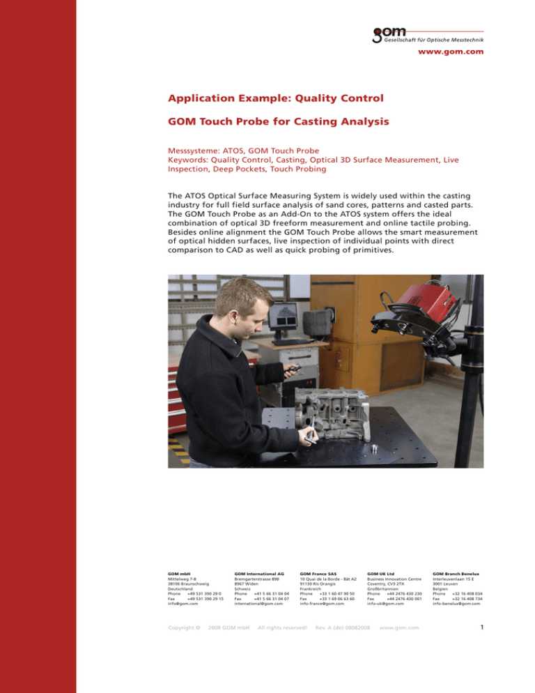
Application Example: Quality Control
GOM Touch Probe for Casting Analysis
Messsysteme: ATOS, GOM Touch Probe
Keywords: Quality Control, Casting, Optical 3D Surface Measurement, Live
Inspection, Deep Pockets, Touch Probing
The ATOS Optical Surface Measuring System is widely used within the casting
industry for full field surface analysis of sand cores, patterns and casted parts.
The GOM Touch Probe as an Add-On to the ATOS system offers the ideal
combination of optical 3D freeform measurement and online tactile probing.
Besides online alignment the GOM Touch Probe allows the smart measurement
of optical hidden surfaces, live inspection of individual points with direct
comparison to CAD as well as quick probing of primitives.
GOM mbH
Mittelweg 7-8
38106 Braunschweig
Deutschland
Phone
+49 531 390 29 0
Fax
+49 531 390 29 15
info@gom.com
Copyright ©
GOM International AG
Bremgarterstrasse 89B
8967 Widen
Schweiz
Phone
+41 5 66 31 04 04
Fax
+41 5 66 31 04 07
international@gom.com
2008 GOM mbH
GOM France SAS
10 Quai de la Borde - Bât A2
91130 Ris Orangis
Frankreich
Phone
+33 1 60 47 90 50
Fax
+33 1 69 06 63 60
info-france@gom.com
All rights reserved!
GOM UK Ltd
Business Innovation Centre
Coventry, CV3 2TX
Großbritannien
Phone
+44 2476 430 230
Fax
+44 2476 430 001
info-uk@gom.com
Rev. A (de) 08082008
www.gom.com
GOM Branch Benelux
Interleuvenlaan 15 E
3001 Leuven
Belgien
Phone
+32 16 408 034
Fax
+32 16 408 734
info-benelux@gom.com
1
ATOS Optical 3D Measurement System
In casting applications the ATOS 3D Digitizer offers various advantages
compared to traditional measuring techniques. The fast full field measuring
technology of ATOS guarantees a fast validation of the object's complete and
complex surface rather than just collecting a few points leaving large unknown
areas (Fig. 1).
Based on the principle of triangulation the ATOS 3D Digitizer projects different
fringe patterns onto the object which are recorded by two cameras (Fig. 2). The
computer automatically calculates the 3D coordinates for each camera pixel of
the scanned surfaces with very high precision and resolution. Each individual
measurement takes approximately 1-2 seconds and is automatically transformed
to a common object coordinate system using previously applied reference
points. During measurement the software checks online for system calibration,
sensor movement or any ambient changes that might affect the measurement.
Fig. 1: Measurement of a
Pattern Plate with ATOS
System
Fig. 2: ATOS Optical
Measuring System for
scanning casted parts
Fig. 3: Non-contact measuring
of sand cores with ATOS
The ATOS 3D optical digitizer is mobile and can simply be transported to the
object so that heavy casts, tools and models can be easily inspected right away
on-site in foundries, tool- and die-shops (Fig. 2). Due to its robust design, the
sensor head is built to perform in harsh and adverse production environments.
As a non contact optical measuring device ATOS is also ideal to check sensitive
sand cores before the casting process (Fig. 3).
The measuring volume can easily be adapted to specific measuring tasks and
object sizes within a few minutes by interchangeable lens sets. Due to this
flexibility, the ATOS system is able to measure objects of various sizes, from
filigree injection-molding components to a complete aircraft. Turntables, robots
or multiple axis motion units are available for automated measurement of
multiple parts (Fig. 2).
ATOS Inspection Software
The ATOS Inspection Software provides a number of functions essential for the
Casting Industry (Fig. 4). In addition to full field 3D shape and dimension
analysis against CAD the software allows calculation of material thickness in
order to check material allowance for further processing. It is possible to control
size and position of basic primitives and also virtual calipers are included.
Inspection sections with tolerance bands are available as well as classical 2D
dimensioning tools. The ATOS reference point system allows moreover checking
of parting surfaces for offset, fitting and proper closing of mould halves.
Copyright ©
2008 GOM mbH
All rights reserved!
Rev. A (de) 08082008
www.gom.com
2
For documentation and further processing the ATOS Inspection Software
includes enhanced reporting and documentation functions and interfaces in
order to generate standard or customized 3D measuring reports or traditional
tables with CMM points (Fig. 5). Results and deviations can be exported to
various formats such as Excel, HTML, Word, etc.
For recurring measuring tasks the software evaluation can be automated using
powerful macros and scripting language.GOM also provides the free ATOS 3D
Viewer and such measuring results can be easily shared with customers or
colleagues from other departments.
Fig. 4: ATOS Inspection Software:
Evaluation examples
Fig. 5: ATOS Inspection Software:
Typical measuring report
GOM Touch Probe
For evaluation of optically hidden surfaces such as water jackets, cooling holes,
deep pockets and deep cylinders parts had to be measured until now on
classical CMMs, a process which is very time-consuming due to necessary fixing
and alignment of the parts.
The GOM Touch Probe as an add-on to the ATOS 3D Digitizer helps to overcome
this obstacle. The handheld Touch Probe enables the user to switch easily
between 3D full-field measurement and online tactile probing of specific single
points (Fig. 6). A time-consuming modification or rebuild of the sensor setup is
not necessary. The GOM touch probe is a calibrated set of point markers which
are optically tracked by the ATOS 3D Digitizing system measuring the online 3D
coordinate of the calibrated probe tip (Fig. 7).
Fig. 6: ATOS System with GOM Touch Probe
Copyright ©
2008 GOM mbH
All rights reserved!
Fig. 7: ATOS sensor head as optical
tracker for point markers of Touch Probe
Rev. A (de) 08082008
www.gom.com
3
Thus a comfortable live inspection of points and primitives is now available.
Tactile probing of geometries such as planes, spheres, cylinders and cones as
well as circular, slotted and rectangular holes and borderline segments is now
possible (Fig. 8, 9). The Touch Probe furthermore allows fast point based
probing against CAD to determine deviations to reference data also in difficult
to access areas (Fig. 10, 11).
Fig. 8: Touch Probing of deep cylinder
Fig. 9: ATOS Inspection Software:
Touch probed Cylinder
Fig. 10: Touch Probing against CAD of a
water-jacket
Fig. 11: ATOS Inspection Software:
Online View of Probing against CAD
The lightweight Touch Probe allows effortless measurement over long periods
and for larger measuring projects. A constant rigid mounting of the part such as
on CMMs is not necessary. Due to the dynamic referencing either part or sensor
can be freely moved to find comfortable positions. The ATOS Software allows
various alignment strategies at any time. The mechanical and cable-free probe
can be operated via a remote control providing high stability and unrestricted
reach. An audio-feedback signalises probed points and elements guaranteeing a
safe workflow.
Copyright ©
2008 GOM mbH
All rights reserved!
Rev. A (de) 08082008
www.gom.com
4
Different touch probe sizes are available for small to large objects (Fig. 12). The
modular concept of the GOM Touch Probe allows an easy adaption for many
different applications via fast interchange of probe heads and extenders (Fig. 13).
In addition the user can create customized touch probes for specific tasks.
Using the GOM Touch Probe is a fast and straight forward measurement process
since all measurements are done within one system and all evaluations (surface
and tactile) are accomplished direct within the ATOS Measuring and Inspection
Software.
Fig. 12: Different sizes of Touch Probe
Fig. 13: Touch Probe for smaller
Measuring Volume
Conclusion
Many complex metrology applications require the combination of full-field and
point based 3D measurement. The GOM Touch Probe is available as an Add-On
to the ATOS 3D Digitizer, combining full-field optical surface measurement and
online tactile probing within one system.
The easy interchange between surface and single point measurement allows
smart measuring of optical hidden surfaces and offers advantages for quick
analysis of individual points and primitives as well as online comparison of
individual points to CAD. ATOS and the GOM Touch probe can be also utilized
to speed up alignment and calibration of parts, fixtures, jigs and gauges.
Copyright ©
2008 GOM mbH
All rights reserved!
Rev. A (de) 08082008
www.gom.com
5


