MAST ARM POLES AND PEDESTALS
advertisement
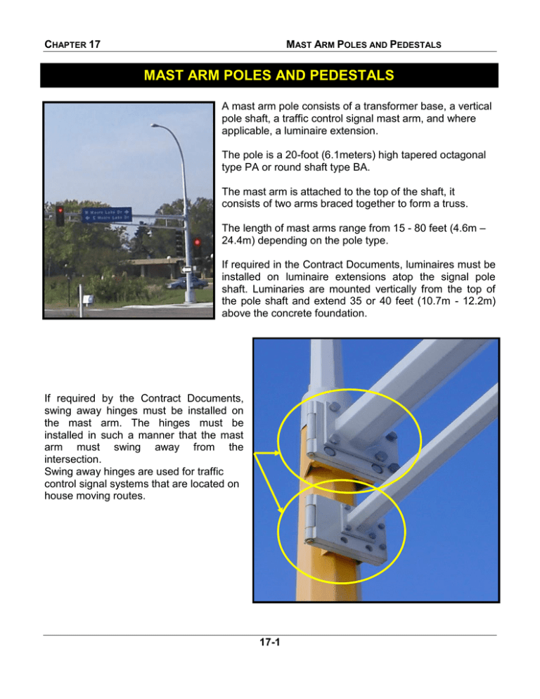
CHAPTER 17 MAST ARM POLES AND PEDESTALS MAST ARM POLES AND PEDESTALS A mast arm pole consists of a transformer base, a vertical pole shaft, a traffic control signal mast arm, and where applicable, a luminaire extension. The pole is a 20-foot (6.1meters) high tapered octagonal type PA or round shaft type BA. The mast arm is attached to the top of the shaft, it consists of two arms braced together to form a truss. The length of mast arms range from 15 - 80 feet (4.6m – 24.4m) depending on the pole type. If required in the Contract Documents, luminaires must be installed on luminaire extensions atop the signal pole shaft. Luminaries are mounted vertically from the top of the pole shaft and extend 35 or 40 feet (10.7m - 12.2m) above the concrete foundation. If required by the Contract Documents, swing away hinges must be installed on the mast arm. The hinges must be installed in such a manner that the mast arm must swing away from the intersection. Swing away hinges are used for traffic control signal systems that are located on house moving routes. 17-1 CHAPTER 17 MAST ARM POLES AND PEDESTALS Before the project begins, the Contractor must furnish to the Engineer, for approval, 4 complete sets of shop drawings as specified in the Contract Documents. The drawings must indicate all member materials and dimensions, section modules of the main component parts, and other pertinent data and calculations. If approved by the Engineer, one set of drawings must be distributed as specified in the Contract Documents. Installation Mast arm poles are plumbed by using the leveling nuts on the foundation anchor rods. Poles must be carefully hoisted into position to avoid damage to the finish. Damaged areas must be repaired as specified in the Contract Documents. The access door of the transformer base must be oriented away from the traffic, as specified in the Contract Documents, to allow service personnel to see the intersection while servicing the base. The mast arm pole standard must be installed and tightened on the concrete foundation anchor rods as specified in the installation procedure as detailed in the Contract Documents. 17-2 CHAPTER 17 MAST ARM POLES AND PEDESTALS Access Cover Access Cover After all mast arm pole standard wiring is complete, the access opening covers must be sealed with 100% clear silicone sealant at final installation. Access Cover Access Cover Access Cover 17-3 CHAPTER 17 MAST ARM POLES AND PEDESTALS The Contractor must furnish and install a stainless steel woven wire cloth that is inserted and wound around the opening at the bottom of the signal pole transformer base in accordance with the requirements in the Contract Documents. The entire stainless steel woven wire cloth assembly must be grounded in accordance with the National Electrical Code (NEC). OUTSIDE VIEW FROM TOP OF CONCRETE FOUNDATION TO OPENING IN THE BOTTOM OF THE TRANSFORMER BASE INSIDE TRANSFORMER BASE VIEW 17-4 CHAPTER 17 MAST ARM POLES AND PEDESTALS Pedestals Pedestal shafts and bases must be unpainted anodized aluminum, unless otherwise specified in the Contract Documents. Pedestals consist of a shaft and a base. The base is designed to break away from the foundation when struck by a vehicle. A re-enforcing collar (wind collar) or a base with an extended neck and set screws is required with each pedestal installation. 3- PIECE RE-INFORCING COLLAR 5” NIPPLE If steel pedestal shafts are specified, the steel shaft must be constructed of a welded 4-1/2 inch (114mm) outside diameter steel tubing and a threaded 5 inch (127mm) long, 4-inch (100mm) standard steel pipe nipple. The nipple is welded to the end of the steel tube and must follow American Welding Society requirements. See Standard Plate 8122 for all requirements. STEEL PEDESTAL SHAFT Apply anti seize compound to all threaded surfaces including set screws, door access bolt, and pedestal shaft. 17-5 CHAPTER 17 MAST ARM POLES AND PEDESTALS The Contract Documents may require pedestal shafts and bases to be painted. All painting of pedestal shafts and bases must be in accordance with the Contract Documents. Pre-painted pedestal shafts or bases that have scratches or other type of damage will not be accepted. The pedestal base must have a threaded top and square transformer base design. For steel pedestal shafts, a 4-inch (100mm) threaded steel pipe nipple must mate with the pedestal base. Four new anchor rods, with washers, and nuts must be furnished with each pedestal base. The pedestal base access door must provide a positive closure with a fixed catch on the inside bottom of the door and a bolt type locking mechanism on the top. Anti-seize compound must be applied to the threads of the stainless steel hex-head bolt. 17-6 CHAPTER 17 MAST ARM POLES AND PEDESTALS One NRTL listed ground lug wire connector must be mounted with a single bolt on the sidewall, 3 inches (90mm) from the door and 8 inches (200mm) above the bottom of the base. The connector must accommodate a No. 6 copper ground wire and must have a slot head screw to connect the ground wire. Pedestal Concrete Foundation Pedestal Screw-in Steel Foundation Installation – The pedestal foundations must be installed as required by the Contract Documents. The pedestal base must be secured to anchorages of the concrete foundations or screw-in steel foundations utilizing nuts and washers as specified in the Contract Documents. The Contract Documents for each traffic control signal system project will dictate whether a pedestal concrete foundation or a pedestal screw-in foundation is to be installed by the Contractor. 17-7 CHAPTER 17 MAST ARM POLES AND PEDESTALS The pedestal base must be plumbed with galvanized steel shims only. See Standard Plate 8129 for additional requirements. The access door of the base must be oriented away from traffic to allow maintenance personnel to see the intersection while servicing the base. 17-8
