Lecture 26 Dielectric Slab Waveguides
advertisement

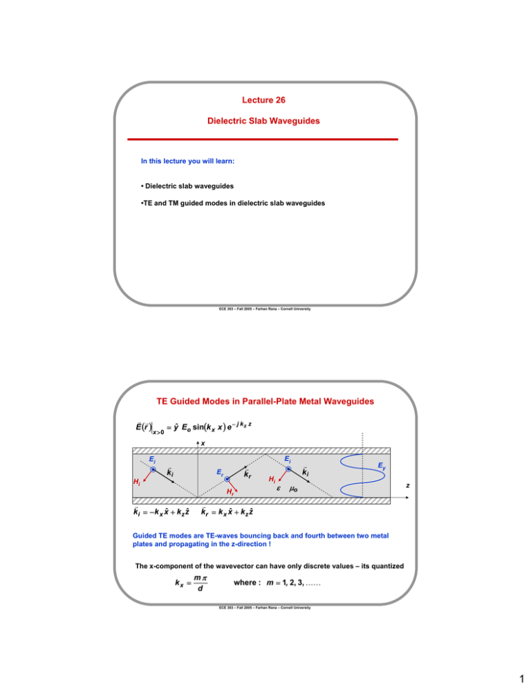
Lecture 26 Dielectric Slab Waveguides In this lecture you will learn: • Dielectric slab waveguides •TE and TM guided modes in dielectric slab waveguides ECE 303 – Fall 2005 – Farhan Rana – Cornell University TE Guided Modes in Parallel-Plate Metal Waveguides r r E (r ) x >0 = yˆ Eo sin(k x x ) e − j k z z x Ei Hi r ki r kr Er Hr r k i = − k x xˆ + k z zˆ Ei Hi ε r ki Ey µo z r k r = k x xˆ + k z zˆ Guided TE modes are TE-waves bouncing back and fourth between two metal plates and propagating in the z-direction ! The x-component of the wavevector can have only discrete values – its quantized kx = mπ d where : m = 1, 2, 3, KK ECE 303 – Fall 2005 – Farhan Rana – Cornell University 1 Dielectric Waveguides - I Consider TE-wave undergoing total internal reflection: Ei x r ki H θi θi r i k i = − k x xˆ + k z zˆ ε1 r kr Er z r k r = k x xˆ + k z zˆ Hr Evanescent wave r r E (r ) x >0 = yˆ E i e − j (− k x x + kz z ) µo + yˆ ΓE i e − j (k x ε 2 µo ε1 > ε 2 x +kz z ) k z2 + k x2 = ω 2 µo ε 1 Γ = 1 when θ i > θc When r r E (r ) θ i > θc : x <0 = yˆ T E i e − j kz z e k x = − jα x −α x x k z2 − α x2 = ω 2 µo ε 2 ECE 303 – Fall 2005 – Farhan Rana – Cornell University Dielectric Waveguides - II x ε2 cladding Evanescent wave Ei Hi r ki θi θi r kr Er µo Ei Hi Hr r ki ε1 µo core ε1 > ε 2 z cladding Evanescent wave ε2 µo One can have a guided wave that is bouncing between two dielectric interfaces due to total internal reflection and moving in the z-direction ECE 303 – Fall 2005 – Farhan Rana – Cornell University 2 Dielectric Slab Waveguides W 2d Assumption: W >> d x cladding core y cladding z ECE 303 – Fall 2005 – Farhan Rana – Cornell University Dielectric Vs Metal Waveguides Ey m=1 ε m=2 µo z Ey Metal Waveguides (modes are tightly confined) ε2 µo ε1 µo ε2 µo cladding Ey Ey core z cladding Dielectric Slab Waveguides (modes are loosely confined) ECE 303 – Fall 2005 – Farhan Rana – Cornell University 3 Dielectric Slab Waveguides – TE Modes: Formal Solution x ε2 µo ε1 µo ε2 µo cladding Ey 2d core Ey z cladding symmetric antisymmetric The TE solutions are of the form: r r E (r ) r r E (r ) r r E (r ) x <d x >d ⎧cos(k x x )⎫ − j k z z = yˆ Eo ⎨ ⎬e ⎩ sin(k x x ) ⎭ = yˆ E1 e x < −d −α x ( x − d ) e The “sine” and “cosine” represent the symmetric and antisymmetric solutions w.r.t. the z-axis − j kz z ⎧+ ⎫ = ⎨ ⎬ yˆ E1 e +α x ( x + d ) e − j k z z ⎩− ⎭ Where: k z2 + k x2 = ω 2 µo ε 1 k z2 − α x2 Given a frequency ω, the values of kz , kx , and αx are still not known 2 = ω µo ε 2 ECE 303 – Fall 2005 – Farhan Rana – Cornell University TE Modes: Boundary Conditions x ε2 µo ε1 µo ε2 µo cladding 2d Ey Ey core z cladding Boundary conditions: (1) At x =± d the component of E-field parallel to the interface (i.e. the y-component) is continuous for all z ⇒ ⎧cos(k x d )⎫ Eo ⎨ ⎬ = E1 ⎩ sin(k x d ) ⎭ (1) (2) At x =± d the component of H-field parallel to the interface (i.e. the z-component) is continuous for all z ⇒ ⎧ − k x sin(k x d )⎫ Eo ⎨ ⎬ = −α x E1 ⎩ k x cos(k x d ) ⎭ (2) ECE 303 – Fall 2005 – Farhan Rana – Cornell University 4 TE Modes: Transcendental Equation x ε2 µo ε1 µo ε2 µo cladding 2d Ey core Ey z cladding Dividing (2) by (1) on the previous slide gives: ⎧ tan(k x d ) ⎫ α x ⎨ ⎬= ⎩ − cot (k x d )⎭ k x But: k z2 + k x2 = ω 2 µo ε 1 k z2 − α x2 α x2 + k x2 = ω 2 µo (ε 1 − ε 2 ) 2 = ω µo ε 2 So we finally get: ⎧ tan(k x d ) ⎫ ω 2 µo (ε 1 − ε 2 ) −1 ⎨ ⎬= k x2 ⎩ − cot (k x d )⎭ Transcendental equation that can be used to solve for kx in terms of the frequency ω ECE 303 – Fall 2005 – Farhan Rana – Cornell University TE Modes: Graphical Solution x ε2 µo ε1 µo ε2 µo cladding 2d Ey core Ey z cladding Graphic solution of the transcendental equation Different red curves for Increasing ω values ⎧ tan(k x d ) ⎫ ω 2 µo (ε 1 − ε 2 ) d 2 −1 ⎨ ⎬= (k x d )2 ⎩ − cot (k x d )⎭ LHS RHS For the m-th TE mode (TEm mode) the value of kx is in the range (depending on the frequency ω): π π 2 2 (m − 1) ≤ k x d ≤ m 0 π π 2 3π 2 2π 5π 2 k xd m = 1, 2, 3,KK ECE 303 – Fall 2005 – Farhan Rana – Cornell University 5 TE Modes: Cut-off Frequencies x ε2 µo ε1 µo ε2 µo cladding Ey 2d core Ey z cladding Different red curves for Increasing ω values ⎧ tan(k x d ) ⎫ ω 2 µo (ε 1 − ε 2 ) d 2 −1 ⎨ ⎬= (k x d )2 ⎩ − cot (k x d )⎭ LHS RHS Cut-off frequency of the m-th TE mode can be obtained by setting the RHS equal to zero for kx d = (m-1)π/2 ωm = π 0 3π 2 π 2 (m − 1)π 5π 2 2π k xd 1 µo (ε 1 − ε 2 ) 2d m = 1, 2, 3,KK ECE 303 – Fall 2005 – Farhan Rana – Cornell University Dielectric Waveguides – What is Cut-off ? x ε2 µo cladding Ei 2d r ki Hi θi θi r kr Er Ei Hi r ki ε1 kz µo core z Hr cladding θi k x ω µo ε 1 ε1 > ε2 ε2 µo So what does “cut-off” really mean? It means that the wave is no longer being guided through total internal reflection since θi < θc A wave will not be guided if: θ i < θc ⇒ ⇒ ⇒ ⇒ ⇒ kz ω µo ε 1 sin(θ i ) < sin(θc ) = ε 2 ε 1 < ε 2 ε1 For the m-th TE mode (TEm mode) the smallest value of kx is: (m − 1) So TEm mode will not be guided if: k z < ω µo ε 2 ω< ω 2 µo ε 1 − k x2 < ω µo ε 2 ω< kx µo (ε 1 − ε 2 ) π 2d ⇒ ωm = kx µo (ε 1 − ε 2 ) k (m − 1)π 2d x= (m −1)π 2d 1 µo (ε 1 − ε 2 ) ECE 303 – Fall 2005 – Farhan Rana – Cornell University 6 TE Modes: Near Cut-off Behavior ε2 µo ε1 µo ε2 µo cladding Ey core Different red curves for increasing ω values z cladding ω >> ω2 (TE2 mode well confined in the core) ε2 π 0 µo cladding Ey core 3π 2 π 2 ε1 µo ε2 µo k xd z cladding ω >≈ ω2 (TE2 mode near cut-off – mode not well confined in the core) ECE 303 – Fall 2005 – Farhan Rana – Cornell University TE Modes: Dispersion Curves x ε2 µo ε1 µo ε2 µo cladding 2d Ey core Ey z cladding How does one obtain dispersion curves? (1) For a given frequency ω find kx using: kz kz = ω TE3 mode dispersion relation µo ε 1 ⎧ tan(k x d ) ⎫ ω 2 µo (ε 1 − ε 2 ) d 2 −1 ⎨ ⎬= (k x d )2 ⎩ − cot (k x d )⎭ TE2 mode dispersion relation kz = ω (2) Then find kz using: k z = ω 2 µo ε 1 − k x2 TE1 mode dispersion relation ω1 ω2 µo ε 2 ω ω3 ECE 303 – Fall 2005 – Farhan Rana – Cornell University 7 TM Modes: Formal Solution x ε2 µo ε1 µo ε2 µo cladding Hy 2d core Hy z cladding The TM solutions are of the form: r r H (r ) r r H (r ) r r H (r ) x <d x >d The “sine” and “cosine” represent the symmetric and antisymmetric solutions w.r.t. the z-axis = yˆ H1 e −α x ( x − d ) e − j k z z x < −d Where: ⎧cos(k x x )⎫ − j k z z = yˆ Ho ⎨ ⎬e ⎩ sin(k x x ) ⎭ ⎧+ ⎫ = ⎨ ⎬ yˆ H1 e +α x ( x + d ) e − j k z z ⎩− ⎭ k z2 + k x2 = ω 2 µo ε 1 Given a frequency ω, the values of kz , kx , and αx are still not known k z2 − α x2 = ω 2 µo ε 2 ECE 303 – Fall 2005 – Farhan Rana – Cornell University TM Modes: Boundary Conditions x ε2 µo ε1 µo ε2 µo cladding 2d Hy Hy core z cladding Boundary conditions: (1) At x =± d the component of H-field parallel to the interface (i.e. the y-component) is continuous for all z ⇒ ⎧cos(k x d )⎫ Ho ⎨ ⎬ = H1 ⎩ sin(k x d ) ⎭ (1) (2) At x =± d the component of E-field parallel to the interface (i.e. the z-component) is continuous for all z ⇒ ⎧ kx ⎫ ⎪⎪ − ε sin(k x d )⎪⎪ αx H Ho ⎨ 1 ⎬=− kx ε2 1 ⎪ cos(k x d ) ⎪ ⎩⎪ ε 1 ⎭⎪ (2) ECE 303 – Fall 2005 – Farhan Rana – Cornell University 8 TM Modes: Transcendental Equation x ε2 µo ε1 µo ε2 µo cladding 2d Hy core Hy z cladding Dividing (2) by (1) on the previous slide gives: ⎧ tan(k x d ) ⎫ α x ε 1 ⎨ ⎬= ⎩ − cot (k x d )⎭ k x ε 2 But: k z2 + k x2 = ω 2 µo ε 1 k z2 − α x2 α x2 + k x2 = ω 2 µo (ε 1 − ε 2 ) 2 = ω µo ε 2 So we finally get: ⎧ tan(k x d ) ⎫ ε 1 ω 2 µo (ε 1 − ε 2 )d 2 −1 ⎨ ⎬= (k x d )2 ⎩ − cot (k x d )⎭ ε 2 Transcendental equation that can be used to solve for kx in terms of the frequency ω ECE 303 – Fall 2005 – Farhan Rana – Cornell University TM Modes: Graphical Solution x ε2 µo ε1 µo ε2 µo cladding 2d Hy core Hy z cladding Graphic solution of the transcendental equation Different red curves for Increasing ω values ⎧ tan(k x d ) ⎫ ε 1 ω 2 µo (ε 1 − ε 2 ) d 2 −1 ⎨ ⎬= (k x d )2 ⎩ − cot (k x d )⎭ ε 2 LHS RHS For the m-th TM mode (TMm mode) the value of kx is in the range (depending on the frequency ω): π π 2 2 (m − 1) ≤ k x d ≤ m 0 π π 2 3π 2 2π 5π 2 k xd m = 1, 2, 3,KK ECE 303 – Fall 2005 – Farhan Rana – Cornell University 9 Fiber Optical Communications: Optical Fibers cladding 9.0 µm core z 125 µm cladding cladding core z Silica (SiO2) core and cladding materials ECE 303 – Fall 2005 – Farhan Rana – Cornell University Integrated Optics 2 um An optical micro-ring filter (separates out light of a particular color) – SEM An optical micro-splitter (splits light two ways) – SEM Slab Waveguide Si Si SiO2 SiO2 Si Si ECE 303 – Fall 2005 – Farhan Rana – Cornell University 10 Integrated Optics: Semiconductor Quantum Well Lasers top metal InP/InGaAsP Waveguide 1 .0 µm thick polyimide layer 3 .0 µm The dielectric waveguide for a semiconductor quantum well laser with metal on top (for electrical connection) is shown A microchip containing several semiconductor laser stripes running in parallel is shown. ECE 303 – Fall 2005 – Farhan Rana – Cornell University 11


