Visible Spectral Analysis for Bremsstrahlung Measurement in High
advertisement

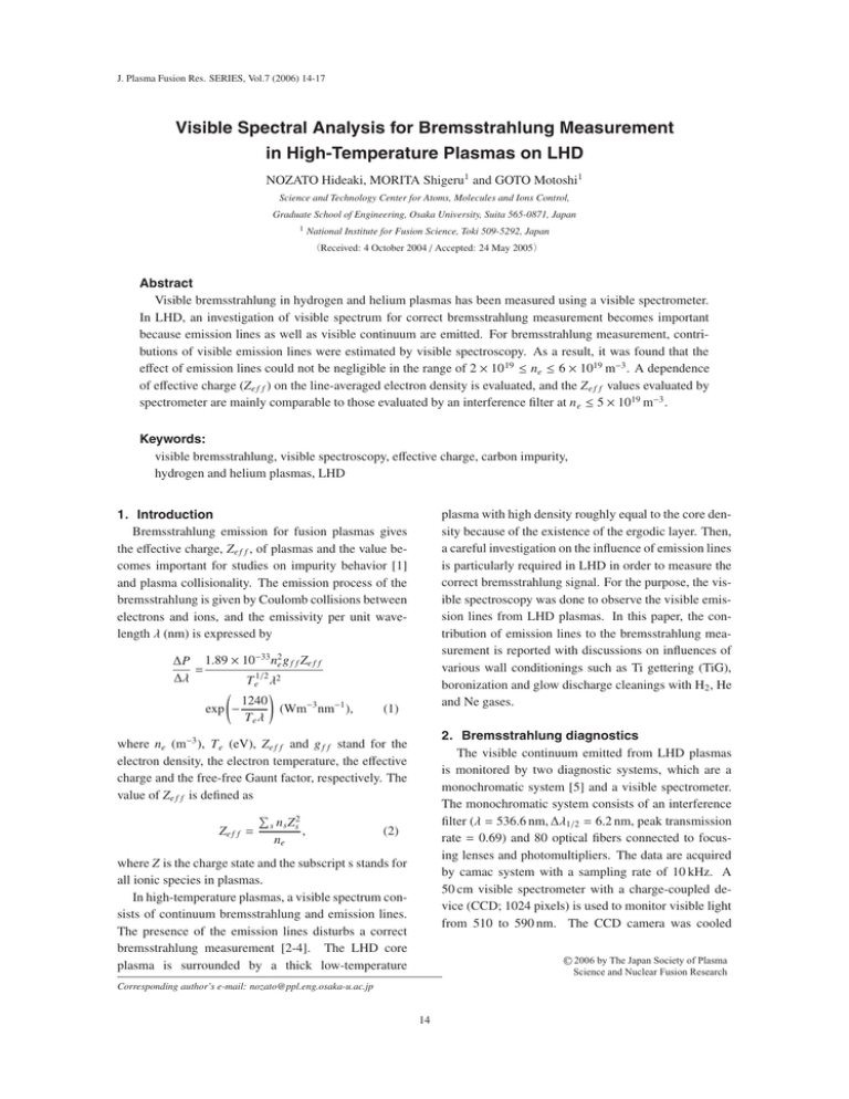
J. Plasma Fusion Res. SERIES, Vol.7 (2006) 14-17 Visible Spectral Analysis for Bremsstrahlung Measurement in High-Temperature Plasmas on LHD NOZATO Hideaki, MORITA Shigeru1 and GOTO Motoshi1 Science and Technology Center for Atoms, Molecules and Ions Control, Graduate School of Engineering, Osaka University, Suita 565-0871, Japan 1 National Institute for Fusion Science, Toki 509-5292, Japan (Received: 4 October 2004 / Accepted: 24 May 2005) Abstract Visible bremsstrahlung in hydrogen and helium plasmas has been measured using a visible spectrometer. In LHD, an investigation of visible spectrum for correct bremsstrahlung measurement becomes important because emission lines as well as visible continuum are emitted. For bremsstrahlung measurement, contributions of visible emission lines were estimated by visible spectroscopy. As a result, it was found that the effect of emission lines could not be negligible in the range of 2 × 10 19 ≤ ne ≤ 6 × 10¹⁹ m−3 . A dependence of effective charge (Ze f f ) on the line-averaged electron density is evaluated, and the Z e f f values evaluated by spectrometer are mainly comparable to those evaluated by an interference filter at n e ≤ 5 × 10¹⁹ m−3 . Keywords: visible bremsstrahlung, visible spectroscopy, effective charge, carbon impurity, hydrogen and helium plasmas, LHD 1.Introduction Bremsstrahlung emission for fusion plasmas gives the effective charge, Ze f f , of plasmas and the value becomes important for studies on impurity behavior [1] and plasma collisionality. The emission process of the bremsstrahlung is given by Coulomb collisions between electrons and ions, and the emissivity per unit wavelength λ (nm) is expressed by ∆P 1.89 × 10⁻³³ n2e g f f Ze f f = ∆λ T e1/2 λ2 1240 exp − (Wm−3 nm−1 ), Teλ plasma with high density roughly equal to the core density because of the existence of the ergodic layer. Then, a careful investigation on the influence of emission lines is particularly required in LHD in order to measure the correct bremsstrahlung signal. For the purpose, the visible spectroscopy was done to observe the visible emission lines from LHD plasmas. In this paper, the contribution of emission lines to the bremsstrahlung measurement is reported with discussions on influences of various wall conditionings such as Ti gettering (TiG), boronization and glow discharge cleanings with H2 , He and Ne gases. (1) 2.Bremsstrahlung diagnostics The visible continuum emitted from LHD plasmas is monitored by two diagnostic systems, which are a monochromatic system [5] and a visible spectrometer. The monochromatic system consists of an interference filter (λ = 536.6 nm, ∆λ1/2 = 6.2 nm, peak transmission rate = 0.69) and 80 optical fibers connected to focusing lenses and photomultipliers. The data are acquired by camac system with a sampling rate of 10 kHz. A 50 cm visible spectrometer with a charge-coupled device (CCD; 1024 pixels) is used to monitor visible light from 510 to 590 nm. The CCD camera was cooled where ne (m−3 ), T e (eV), Ze f f and g f f stand for the electron density, the electron temperature, the effective charge and the free-free Gaunt factor, respectively. The value of Ze f f is defined as Ze f f = s n s Z s2 , ne (2) where Z is the charge state and the subscript s stands for all ionic species in plasmas. In high-temperature plasmas, a visible spectrum consists of continuum bremsstrahlung and emission lines. The presence of the emission lines disturbs a correct bremsstrahlung measurement [2-4]. The LHD core plasma is surrounded by a thick low-temperature C Corresponding author’s e-mail: nozato@ppl.eng.osaka-u.ac.jp 14 2006 by The Japan Society of Plasma Science and Nuclear Fusion Research Visible Spectral Analysis for Bremsstrahlung Measurement in High-Temperature Plasmas on LHD down to −20 ◦ C, at which the noise level was negligible. In the present experiment, observation positions in both diagnostics are nearly close along the equatorial plane of LHD. The spatial resolution defined by the focal lenses was 5 cm at plasma center for both cases. The contribution of emission lines can be, thus, evaluated from the wavelength dependence of λ−2 exp(1/λ) as known in eq. (1). traced by thick solid lines. In hydrogen plasmas after TiG, many C I emission lines and a charge-exchange recombination line of C VI (528.9 nm) are seen in the spectrum. In helium plasmas after TiG, the He II line is strongly emitted at λ = 541.2 nm, while the C VI line becomes considerably weak. In hydrogen plasmas after boronization, however, the strong carbon emission lines are disappeared. For quantitative evaluations, the bremsstrahlung emission and the visible line contribution estimated 1.0 2 spectra Intensity (103 counts) CVI brems. filter 0.8 0.6 1 0.4 0.2 (a) H plasma 2 1.0 Intensity (10 3 counts) (b) He plasma HeII 0.6 1 0.4 0.2 0 0 2 1.0 Intensity (103 counts) 2 0.6 1 0.4 0.2 0 520 103 450 500 550 600 650 Wavelength (nm) 0.8 CII HeI CII H H CIII 104 HeII H Intensity (counts) 106 0.8 Filter transmission rate 0 Filter transmission rate 2 0 (c) H plasma (Bor.) 105 Filter transmission rate 3.Results of spectral analysis and discussions In LHD, almost all visible emission lines are radiated in the ergodic layer located outside the last closed flux surface [6]. The visible lines consist of many elements such as fuel gases, carbon, oxygen, metals and Ne and Ar puffed for diagnostic use. A typical example of visible spectra measured by the spectrometer with 150 grooves/mm grating is presented in Fig. 1, which is taken in a hydrogen plasma with Ti-gettering (TiG). Analyzing the visible spectra, it is suggested that the wavelength range of 530 to 550 nm or the vicinity of 630 nm is a unique candidate for the visible bremsstrahlung measurement. The free-spectral range of 530-550 nm is wider than other ones. The wavelength range of 530-550 nm seems to be the best choice for the visible bremsstrahlung measurement. In order to analyze the contribution of emission lines in detail, high-resolution visible spectroscopy was made using 600 grooves/mm grating for various discharge conditions. Figure 2 shows visible spectra recorded from (a) hydrogen and (b) helium plasmas after TiG and (c) hydrogen plasma after boronization. Here, the bremsstrahlung emissions denoted by dashed lines are approximated as λ−2 exp(1/λ), which is derived by Eq. (1). The transmission rate of the interference filter is 530 540 550 560 Wavelength (nm) 570 0 580 Fig. 2 Visible spectra (thin solid lines) in (a) hydrogen and (b) helium plasmas after TiG., and (c) hydrogen plasmas after boronization. Dashed and thick solid lines indicate bremsstrahlung emissions and transmission rate of interference filter, respectively. 700 Fig. 1 Typical example of visible spectrum in hydrogen plasmas after TiG. 15 Visible Spectral Analysis for Bremsstrahlung Measurement in High-Temperature Plasmas on LHD from visible spectra are plotted in Fig. 3 as a function of electron density. The solid line in the figure indicates the square dependence of bremsstrahlung signal. Since the intensity of visible emission lines cannot be negligible in a range of the electron densities, the true bremsstrahlung emission can be obtained by evaluating the dependence of visible continuum on the wavelength. Thus, the bremsstrahlung measurement only using the present interference filter seems to be difficult. Under the present situation, the spectroscopy of visible light is needed for an exact Ze f f evaluation. Line-averaged Ze f f are, thus, obtained as a function of electron density for H2 and He plasmas after TiG and boronization as shown in Fig. 4. The Ze f f values estimated from only the visible spectrum are shown in the figure, which are denoted with ’Spectrometer’ in the bracket. ’Filter’ indicates the Ze f f evaluated from the monochromatic measurement, and the values are also plotted as a reference only in high electron density regime. Interference filter with 3.0 nm of FWHM is normally used for visible bremsstrahlung measurement [3,7,8]. However, an interference filter with 6.2 nm of FWHM is adopted because of roughly 50 % light loss by a 10 cm quartz glass and 100 m optical fiber band in our bremsstrahlung diagnostics. As a result, the Ze f f values by ’Filter’ are comparable to those by ’Spectrometer’ at ne ≤ 5×10¹⁹ m−3 . The low-density limit for the Ze f f measurement seems to be 2 × 10¹⁹ m−3 , and the bonized wall-coating in such a density regime would be effective for a reduction of high-Z impurity contamination. Moreover, it is a little surprise to see in the figure that the Ze f f have the same values for H2 and He discharges. As one of possible reasons, the carbons in hydrogen plasma increase much greater than that in helium plasmas. As known in Fig. 2(a), the strong emission line of C VI (528.9 nm) is observed, which shows the amount of fully ionized carbon ions in core plasma. Emission lines from carbon molecules are also observed in hydrogen discharges. 5 Visible line contribution Estimated bremsstrahlung Intensity (104 counts) 4 3 2 1 4.Summary For visible bremsstrahlung measurement in LHD, the wavelength spectrum was obtained from visible spectroscopy, and the contribution of emission lines was analyzed in various discharge conditions. Strong emission lines such as C VI (528.9 nm) and He II (541.2 nm) were observed in hydrogen and helium plasmas, respectively. The contribution of emission lines, which occupied 10 − 50 % of visible emissions through an interference filter at 2 × 10¹⁹ ≤ ne ≤ 6 × 10¹⁹ m−3 , was estimated by high-resolution spectroscopic measurement. The line contribution was found not to be negligible for the visible bremsstrahlung measurement using the interference filter. Moreover, any large improvement was not observed for the variety of discharge cleaning conditions, although only the boronization reduced the spectral line contribution. In future work, the radial distribution of the line contribution has to be measured in order to take the Ze f f profile, especially for the edge Ze f f profile. An alternative idea may be needed e.g. changing the filter wavelength to infrared light. 0 0 1 2 3 4 ne (1019 m-3) 5 6 Fig. 3 Intensities of bremsstrahlung and emission lines, estimated from visible spectrum, as a function of line-averaged electron density. 5 H TiG (Filter) H TiG (Spectrometer) H Bor. (Spectrometer) He TiG (Filter) He TiG (Spectrometer) Zeff 4 3 2 1 0 2 4 6 19 ne (10 m-3) 8 10 Fig. 4 Line-averaged Zeff against line-averaged electron density (○, ●, +: H2 plasmas after TiG and boronization, ■, □: He plasmas after TiG). Each ’Spectrometer’ and ’Filter’ indicates Zeff values, which are estimated by visible spectrometer and monochromatic measurement using an interference filter. [1] [2] 16 References H. Nozato, S. Morita, M. Goto et al., Phys. Plasmas 11, 1920 (2004). M.E. Foord, E.S. Marmar and J.L. Terry, Rev. Visible Spectral Analysis for Bremsstrahlung Measurement in High-Temperature Plasmas on LHD [3] [4] [5] Sci. Instrum. 53, 1407 (1982). F. Orsitto, M.R. Belforte, M. Borra et al., Rev. Sci. Instrum. 68, 1024 (1997). S. Morita and J. Baldzuhn, Max Planck Institute IPP-report (Garching, Germany), No.199 (1995). H. Nozato, S. Morita, M. Goto et al., J. Plasma Fusion Res. Series 5, 442 (2002). [6] [7] [8] 17 M. Goto and S. Morita, Phys. Rev. E 65, 026401 (2002). E.S. Marmar, R.L. Boivin et al., Rev. Sci. Instrum. 72, 940 (2001). D.G. Whyte, M.R. Wade, D.F. Finkenthal et al., Nucl. Fusion 38, 387 (1997).


