Non-uniform Illumination Correction in Transmission
advertisement

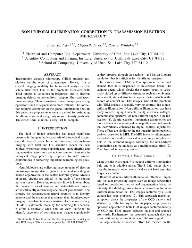
NON-UNIFORM ILLUMINATION CORRECTION IN TRANSMISSION ELECTRON MICROSCOPY Tolga Tasdizen1,2,3 , Elizabeth Jurrus2,3 , Ross T. Whitaker2,3 1 2 Electrical and Computer Eng. Department, University of Utah, Salt Lake City, UT 84112 Scientific Computing and Imaging Institute, University of Utah, Salt Lake City, UT 84112 3 School of Computing, University of Utah, Salt Lake City, UT 84112 ABSTRACT Transmission electron microscopy (TEM) provides resolutions on the order of a nanometer. Hence, it is a critical imaging modality for biomedical analysis at the sub-cellular level. One of the problems associated with TEM images is variations in brightness due to electron imaging defects or non-uniform support films and specimen staining. These variations render image processing operations such as segmentation more difficult. The correction requires estimation of the global illumination field. In this paper, we propose an automatic method for estimating the illumination field using only image intensity gradients. The closed-form solution is very fast to compute. I. INTRODUCTION The field of image processing has made significant progress in the quantitative analysis of biomedical images over the last 20 years. In certain domains, such as brain imaging with MRI and CT, scientific papers that test clinical hypotheses using sophisticated image filtering and segmentation algorithms are not uncommon. Research in biological image processing is poised to make similar contributions in answering important neurobiological questions. Neurobiologists are collecting large amounts of electron microscopy image data to gain a better understanding of neuron organization in the central nervous system. Models of neural circuits are critical to the study of the central nervous system. However, relatively little is known about the connectivities of neurons and state-of-the-art models are insufficiently informed by anatomical ground truth. The strategy for reconstructing neural circuitry is to identify neurons and the synapses that connect them in microscopic imagery. Serial-section transmission electron microscopy (TEM) is a desirable modality for achieving this because it offers a relatively wide field of view—sufficient to identify large sets of cells that may wander significantly We thank Dr. Robert Marc and Dr. Eric Jorgensen for providing us with TEM images. This work was supported by NIH R01 EB005832. as they progress through the sections—and has an in-plane resolution that is sufficient for identifying synapses. In serial-section TEM, a thin specimen is cut and stained, then it is suspended in an electron beam. The staining agent, which blocks the electron beam, is selectively picked up by different structures such as membranes. As a result, stained structures appear darker which is the source of contrast in TEM images. One of the problems with TEM images is spatially varying contrast due to nonuniform illumination. Non-uniform illumination can have many sources: aging filaments, faulty reference voltages, contaminated apertures, or non-uniform support film fabrication [1]. Subtle electron illumination asymmetries are more evident at moderate-to-low magnifications and are often inadvertently enhanced by digital contrast adjustment. These effects are similar to the the intensity inhomogeneity problem observed in MRI. The MRI intensity inhomogeneity problem is manifested as a slowly varying multiplicative field in the acquired images. Similarly, the non-uniform illumination can be modeled as a multiplicative effect [2]. The observed image is given as f (x, y) = s(x, y)I(x, y) + n(x, y), (1) where s is the true signal, I is the non-uniform illumination field and n is additive noise. The I field varies slowly over the image; in other words, it does not have any high frequency content. Removal of non-uniform illumination effects is important for later processing stages such as image registration based on correlation metrics and segmentation based on intensity thresholding. An automatic correction for nonuniform illumination in TEM images captured by a CCD camera has been proposed [2]. This approach makes assumptions about the properties of the CCD camera and stationarity of the true signal. In this paper, we propose an approach applicable to both TEM images captured directly by CCD and TEM images captured on film and scanned afterwards. Furthermore, the proposed approach does not make stationarity assumptions about the true signal. A large amount of research effort has focused on the intensity inhomogeneity problem in MRI. A good review of these methods can be found in [3]. Approaches using tissue class information [4] and combining the inhomogeneity correction with segmentation [5], [6], [7] have been proposed. Other methods perform inhomogeneity correction based on intensity gradients and entropy [8], [9], [10]. MRI intensity inhomogeneity correction approaches that rely on parametric class properties are not useful for TEM images because histograms of cellular TEM images do not have well separated classes. However, methods based on image gradients are suitable for adaptation to TEM images. II. METHODS II-A. Illumination model Randall et al. [2] propose a radial model for the illumination. This is motivated by the observation that the electron beam has a radially symmetric nature. However, the estimation of a radial model requires knowing the precise position of the electron beam’s center, which is not necessarily the center of the image. In [2], this is accomplished by the focus adjustment circle that is available on images captured with a CCD camera. Unfortunately, this focus adjustment circle is not present in TEM images captured on film and scanned. We propose a more general model based on the bivariate polynomial of degree N : j=i i=N XX ˆ y; Γ) = exp I(x, γi−j,j xi−j y j , (2) i=0 j=0 where Γ is the vector of model parameters γ. The motivation for the use of the exponential term is two-fold. First, it guarantees that the illumination model will always evaluate to a non-negative number. Second, it presents an advantage in parameter estimation as will be described in Section II-B. II-B. Model Parameter Estimation After fixing the degree (N ) of the polynomial model in equation 2, estimation of the non-uniform illumination field is reduced to the estimation of the γ parameters. In [2], a direct estimation of parameters is proposed. This approach requires two assumptions: (i) the illumination field I is constant over local neighborhoods, and (ii) the mean value of s in the local neighborhoods is constant over the entire image. The first assumption is always valid owing to the physics of TEM imaging; however, the second assumption fails depending on the type of specimen being imaged. For instance, there can be large structures in TEM images that are darker on average than the rest of the image, see Figure 1. We propose an indirect method of parameter estimation based on the intensity gradients instead of intensity means. Our approach fits the gradient of the illumination model described by equation 2 to those gradients of the image that are most likely to arise from contribution of the true illumination.This is explained in detail next. The gradient of I, which are needed to fit the model parameters, is not directly observable. On the other hand, the gradient of the observed signal,∇f , has three contributing components: 1) Edges of distinct objects: Large in magnitude; Spatially not smooth, but organized geometrically. 2) Gradients due to noise: Varying magnitudes; Spatially not smooth and unorganized (high frequency). 3) Gradients of I: Small magnitude and slowly varying (low frequency). Our goal is to eliminate the first two kinds of gradients, and fit the model in equation 2 only to the gradients of I. We begin by convolving the observed image with a Gaussian kernel Kσ . If the standard deviation σ is chosen large enough, we can assume that the remaining contribution of the noise process n in the filtered signal is negligible: fσ = (sI)σ + nσ ≈ (sI)σ , (3) where fσ denotes the 2D convolution of image f with a Gaussian kernel of standard deviation σ pixels. Furthermore, the convolution of the product of s and I with the Gaussian kernel Kσ can be rewritten in a simpler form. Since I is slowly varying, it is approximately constant in the Gaussian kernel’s region of support. Therefore, equation 3 can be simplified as: Z fσ (x) = s(x + u)I(x + u)Kσ (u)du (4) Z ≈ I(x) s(x + u)Kσ (u)du (5) = I(x)sσ (x), where x denotes the image coordinates (x,y). To transform the multiplicative nature of the illumination field into an additive one, we now take the logarithm of the filtered signal: log fσ (x) = log I(x) + log sσ (x). (6) Taking the gradient of both sides, we get ∇ log fσ (x) = ∇ log I(x) + ∇ log sσ (x). (7) ˆ Let g(x) = log fσ (x) and L̂(x; γ) = log I(x). Then we set up the following penalty function: E(Γ) = P X 2 w(xi ) ∇g(xi ) − ∇L̂(xi ) , (8) i=1 where i enumerates all image pixels and P is the total number of pixels in the image. The parameters of the illumination model are found by minimizing this energy, but the key point is the selection of weights w(xi ). The gradient of log I can not be isolated exactly from the gradient of log sσ ; however, we know that latter is dominant in pixels where an edge is present. Therefore, to decrease the effect of such pixels in the penalty function to be minimized, we define the weights w(xi ) in equation 8 as || ∇fσ (x) || . (9) w(x) = exp − µ2 The penalty function in equation 8 is written in terms of the model parameters γ by substituting equations 10 and 11 for ∇L̂. This is a least-squares fitting problem with a closedform solution. Equations 10 and 11 can be rewritten in matrix form This equation assigns monotonously decreasing weights to pixels with larger gradient magnitudes; the parameter µ controls the rate of decline. By an appropriate choice of µ, edge pixels in sσ can be assigned much smaller weights than non-edge pixels. Finally, the corrected image can be computed by dividing the original image by the exponential of the estimated illumination model. A similar idea was proposed by Samsonov et al. [10] for MRI intensity inhomogeneity correction. The first important difference of our method from the one proposed in [10] is the method of identifying ∇ log I. In that work, Samsonov et al. use anisotropic diffusion [11] to filter the image. Then, the gradient magnitude image is thresholded to remove edge pixels. However, anisotropic diffusion is designed to filter piece-wise constant images. While MRI falls into this category, TEM images of cells (and textured images in general) violate this principle. Therefore, anisotropic diffusion filtering is not a viable option for our application. As discussed above, we use Gaussian filtering combined with an appropriate weighting in the energy equation (8) to eliminate gradients due to edges and noise from the polynomial fit. The second difference is in the use of global histogram information. Samsonov et al. minimize a weighted combination of the gradient fitting and the energy of the histogram power spectrum [10]. The weight for the histogram energy term is negative; therefore, it is being maximized while the gradient fitting energy is being minimized. Due to the presence of this non-linear term in the energy, an iterative solution is required to estimate γ. By dropping this term, we obtained an energy (equation 8) that could be solved very fast in a non-iterative (closedform) manner as explained next. where Γ is the vector of parameters in lexographic order. For a polynomial of degree N in two variables (x, y), there are (N + 1)(N + 2)/2 parameters. Since parameter for the constant term γ0,0 does not appear in equations 10 and 11, it is dropped from Γ. Hence, Γ is a (N +1)(N +2)/2−1 dimensional vector. The row vectors Q(x) and R(x) are the corresponding monomial terms from equations 10 and 11, respectively: 1 0 2x y 0 . . . N xN −1 . . . 0 Q(x) = 0 1 0 x 2y . . . 0 . . . N y N −1 . R(x) = II-C. Implementation Taking the gradient of logarithm of the illumination model in equation 2, we can derive the components of ∇L̂: ∂ L̂ (x; Γ) dx ∂ L̂ (x; Γ) dy = j=i i=N XX = i=1 j=0 = Q(x)Γ (12) = R(x)Γ. (13) Let M be the 2P × (N + 1)(N + 2)/2 − 1 matrix built by concatenating the row vectors Q and R for all pixel locations: Q(x1 ) ... Q(xP ) (14) M= R(x1 ) ... R(xP ) Finally, define the vector of the logarithm of the image intensities ∂g dx (x1 ) ... ∂g (x ) P g = dx ∂g dy (x1 ) ... ∂g dy (xP ) derivatives from the . (15) Then the energy function in equation 8 can be rewritten as 2 E(Γ) = kMΓ − gk . (16) The solution to this least-squares optimization problem is found closed-form as −1 T Γ = MT M M g. (17) III. RESULTS AND DISCUSSION (i − j)γi−j,j xi−j−1 y j (10) i=1 j=0 j=i i=N XX ∂ L̂ (x; γ) dx ∂ L̂ (x; γ) dy jγi−j,j xi−j y j−1 (11) Figure 1(a) shows sample TEM images from the celegans ventral nerve cord and the rabbit retina. The first column shows actual TEM images, the second column shows the corrected image and the third column shows the Original image Corrected image Estimated illumination Fig. 1. Examples of illumination correction for TEM images of the c-elegans (rows 1-3) and rabbit retina (row 4). estimated illumination field. Effects of a non-homogeneous illumination field is apparent in all of the examples shown in the first column. For instance, for the TEM images shown in the first two rows, central locations are brighter whereas for the TEM image in the last row structures in the right side of the image appear brighter than those on the left. However, also notice there are structures in these images that are naturally darker than other cells. This is not a case of non-uniform illumination and should not be corrected. Our approach solves this problem in two ways: 1) the polynomial illumination model proposed in this paper has a low number of degrees of freedom so it can not capture local changes in intensity and 2) the weights in equation 9 will be low for the edges of these darker structures since they reflect a sharp transition from low to high intensity values. The illumination corrected image for a 1000 × 1000 image takes approximately 1 − 2 seconds to compute on a PC. To further demonstrate the utility of our illumination correction method, we will use a simple membrane detection example. Cell membranes appear darker in TEM images than their surroundings; however, their absolute intensity level is impacted by the illumination field. Figure 2 shows the results of a simple thresholding experiment to identify the cell membrane for the image shown in the last row of Figure 1. As expected, the results with the illumination corrected image (Figure 2b) are found to be spatially more consistent than the results with the original image (Figure 2a). In this paper, we proposed an automatic illumination correction for TEM images that does not rely on strong assumptions about the true signal. The method draws on ideas from the MRI intensity inhomogeneity correction method introduced in [10]; however, it uses a different strategy for identifying image gradients due to non-uniform illumination that is more suitable for TEM images. Furthermore, we proposed an energy function with a closed-form solution that can be computed very fast. IV. REFERENCES [1] G. Meek, Practical electron microscopy for biologists, Wiley & Sons, London, 1976. [2] G. Randall, A. Fernandez, O. Trujillo-Cenoz, G. Apelbaum, M. Bertalmio, L. Vazquez, F. Malmierca, and P. Morelli, “Image enhancement for a low cost tem acquisition system,” in SPIE Proc. Three-Dim. and Multidimensional Microscopy: Image Acquisition and Processing V, 1998, vol. 3261. [3] U. Vovk, F. Pernus, and B. Likar, “A review of methods for correction of intensity inhomogeneity in mri,” IEEE Transactions on Medical Imaging, vol. 26, no. 3, pp. 405– 421, 2007. [4] M. Styner, C. Brechbuhler, G. Szekely, and G. Gerig, “Parametric estimate of intensity inhomogeneities applied to mri,” IEEE Trans. Medical Imaging, vol. 19, no. 3, pp. 153–165, 2000. [5] W. M. Wells, W. E. L. Grimson, R. Kikinis, and F. A. Jolesz, “Adaptive segmentation of mri data,” IEEE Trans. Medical Imaging, vol. 15, no. 4, pp. 429–443, 1996. (a) (b) Fig. 2. Result of thresholding (a) original image, (b) illumination corrected image. [6] R. Guillemaud and M. Brady, “Estimating the bias field of mr images,” IEEE Trans. Medical Imaging, vol. 16, no. 3, pp. 238–251, 1997. [7] K. Van Leemput, F. Maes, D. Vandermeulen, and P. Seutens, “Automated model-based bias field correction of mr images of the brain,” IEEE Trans. Medical Imaging, vol. 18, pp. 885–896, 1999. [8] J. G. Sled, P. Zijdenbos, and A. C. Evans, “A nonparametric method for automatic correction of intensity nonuniformity in mri data,” IEEE Trans. Medical Imaging, vol. 17, pp. 87–97, 1998. [9] B. Likar, M. A. Viergever, and F. Pernus, “Retrospective correction of mr intensity inhomogeneity by information minimization,” IEEE Trans. Medical Imaging, vol. 20, no. 12, pp. 1398–1410, 2001. [10] A. A. Samsonov, R. T. Whitaker, E. G. Kholmovski, and C. R. Johnson, “Parametric method for correction of intensity inhomogeneity in mri data,” in Proc. of 10th Annual Scientific Meeting of Int. Society for Magnetic Resonance in Medicine, 2002, p. 154. [11] P. Perona and J. Malik, “Scale-space and edge detection using anisotropic diffusion,” IEEE Trans. Pattern Anal. Mach. Intell., vol. 12, no. 7, pp. 629–639, 1990.

