SJJ Embedded Micro Solutions
Version 1
MSGBB557TA – 7 Color Blinking LED Circuit Setup and Usage
By Sean D. Liming
Managing Director
SJJ Embedded Micro Solutions
November 2009
MODE
I was looking to create some LED lighting effects for some holiday decorations. I came across an
interesting LED that produced 7 colors and a blinking effect. The Micro Electronics LTD
(http://www.microelectr.com.hk/) MSGBB557TA contains a red, green, and blue LEDs tied to an
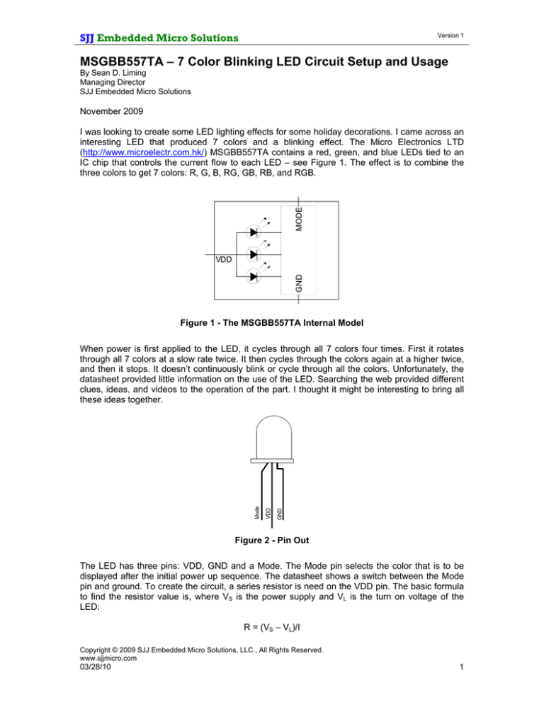
IC chip that controls the current flow to each LED – see Figure 1. The effect is to combine the
three colors to get 7 colors: R, G, B, RG, GB, RB, and RGB.
GND
VDD
Figure 1 - The MSGBB557TA Internal Model
When power is first applied to the LED, it cycles through all 7 colors four times. First it rotates
through all 7 colors at a slow rate twice. It then cycles through the colors again at a higher twice,
and then it stops. It doesn’t continuously blink or cycle through all the colors. Unfortunately, the
datasheet provided little information on the use of the LED. Searching the web provided different
clues, ideas, and videos to the operation of the part. I thought it might be interesting to bring all
these ideas together.
Figure 2 - Pin Out
The LED has three pins: VDD, GND and a Mode. The Mode pin selects the color that is to be
displayed after the initial power up sequence. The datasheet shows a switch between the Mode
pin and ground. To create the circuit, a series resistor is need on the VDD pin. The basic formula
to find the resistor value is, where VS is the power supply and VL is the turn on voltage of the
LED:
R = (VS – VL)/I
Copyright © 2009 SJJ Embedded Micro Solutions, LLC., All Rights Reserved.
www.sjjmicro.com
03/28/10
1
SJJ Embedded Micro Solutions
Version 1
For this circuit I chose to use a 9V battery since I had both the battery connector and battery
already available. The LED’s forward voltage (operating supply) is 3.2V typical and the forward
current is 35mA typical. The resistor value is found using the formula:
R = 165Ω = (9 – 3.2)/0.035
180Ω is the closest resistor available. I chose to limit the current further and use 330Ω ½ watt
resistor. Figure 3 shows the final circuit.
U1
VDD
GND
330ohm
9V
BAT1
R1
SW1
MODE
MFG Part No.: MSGBB557TA
Radio Shack: 276-016
Figure 3 - Basic Circuit for the MSGBB57TA
The mode switch (SW1) is a momentary switch, and it is closed to start. After the circuit has
powered up and cycled through the colors 4 times (2 slowly and 2 fast), the LED stops with the
RED LED on. The mode switch (SW1) is used to set the state of the LED. If the switch is connect
so Mode is connected to ground, the LED will turn off. Press the switch again, the Green LED
turns on. Another press will turn the LED off. The table below shows the sequence after the RED
LED is on:
Copyright © 2009 SJJ Embedded Micro Solutions, LLC., All Rights Reserved.
www.sjjmicro.com
03/28/10
2
SJJ Embedded Micro Solutions
Version 1
SW1 Press
LED State
1
2
3
4
5
6
7
8
9
10
11
12
13
14
Off
Green On
Off
Blue On
Off
Red and Green On
Off
Green and Blue On
Off
Red and Blue On
Off
Red, Green, and Blue On
Off
1Hz Cycle through all 7 colors
continuously
Off
Red On – start cycle
15
16
Table 1 – Mode Switch Sequencing For Figure 3 Circuit
The LED can be set to cycle through all 7 colors continuously once the proper mode is set. Using
the mode switch appears to be what the manufacturer intended. Connecting the Mode switch to
the GPIO of a micro controller would make for an interesting exercise.
MODE
Someone else on the web found an interesting characteristic. When they used ~600Ω series
resistor, the LED would stay in the initial 7 color power on rotation indefinitely. I found the same
characteristic using an 800Ω resistor – see Figure 4. The higher resistance starves the internal
LED circuit enough so it resets to the initial one shot power on sequence. Probably not the
intended use, but it is an interesting trick if you want the 7 colors to continuously rotate on startup.
R2
GND
9V
BAT2
800ohm
U2
VDD
Figure 4 - Continues 7 Color Rotation Circuit
The MSGBB557TA is an interesting LED, but the lack of documentation appears to have
stumped some folks. Hopefully, the information provided here will be useful for those using the
device in their projects.
Copyright © 2009 SJJ Embedded Micro Solutions, LLC., All Rights Reserved.
www.sjjmicro.com
03/28/10
3


