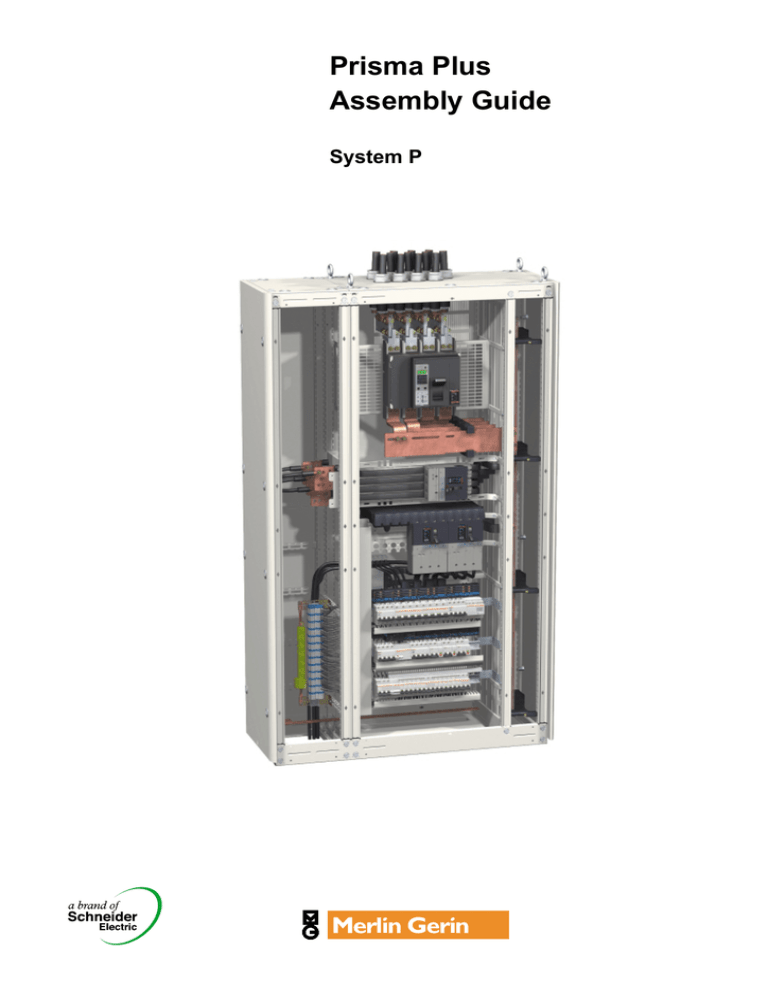
Prisma Plus
Assembly Guide
System P
Preface
This guide proposes a procedure for assembling the Prisma Plus “System P”.
We have designed it to help you successfully complete your first projects. It ensures
that assembling and cabling staff, for whom it is intended, will benefit from the
considerable experience in this field acquired by Schneider Electric and its
customers. In short, it is an essential workshop tool.
There are several approaches for assembling Prisma Plus components. In this
guide we propose one approach which you can add to according to your
professional organisation and experience.
This guide does not replace the technical manuals supplied in the packing of each
component, but recommends an assembly sequence for the components and
provides information to complement that given in the manuals (assembly tips and
tricks, specific assembly recommendations, warnings, etc.).
Assembly guide – System P – Version 4.0
1
Merlin Gerin
Contents
Preface ........................................................................................ 1
Presentation of the components ............................................... 4
Instructions for use .................................................................... 6
Tools
Assembling and cabling tools ............................................................................... 7
Inspection tools....................................................................................................... 7
Identify and sort the components ............................................. 8
Assemble the frameworks ......................................................... 9
Install the busbars
Installing the horizontal busbar........................................................................... 10
Installing the vertical busbar ............................................................................... 10
Coupling the busbars ........................................................................................... 12
Installing the PE and PEN .................................................................................... 13
Marking the busbars ............................................................................................. 13
Assembling the form 2 barrier for horizontal busbar ....................................... 13
Assembling the form 2 side barrier for vertical busbar.................................... 14
Install the mounting plates
Installing the mounting plates and switchgear.................................................. 15
Checking switchgear position ............................................................................. 16
Run and cable the power circuits
Power cables ......................................................................................................... 17
Installing the secondary distribution blocks ..................................................... 19
Installing the connection terminal blocks and the earth bars.......................... 20
Installing the wiring running accessories .......................................................... 20
Fitting the protection devices.............................................................................. 21
Run and cable the low power and auxiliary circuits
Installing the devices on door or front plate...................................................... 22
Installing the wiring running accessories .......................................................... 22
Cabling the auxiliary circuits ............................................................................... 22
Closing the trunking and wiring running accessories...................................... 22
Inspect the switchboard
Final factory inspection........................................................................................ 23
Install the partitioning
Installing the incoming unit partitioning ............................................................ 24
Installing the barriers for the incoming unit connections ................................ 24
Installing the form 3 horizontal barriers ............................................................. 24
Installing the bar duct barriers ............................................................................ 24
Finish and fit the switchboard with panels
Cleaning the switchboard .................................................................................... 25
Finishing the front panel ...................................................................................... 25
Installing the front panel on the framework ....................................................... 25
Fitting the switchboard panels ............................................................................ 26
Pack the switchboard
Packing .................................................................................................................. 27
Assembly guide – System P – Version 4.0
2
Merlin Gerin
Assembly guide – System P – Version 4.0
3
Merlin Gerin
Presentation of the components
Framework
1. Framework upright
2. Top cross-member
3. Bottom cross-member
4. Cable compartment upright
5. Roof
Mounting plates and switchgear
6. Mounting plate support
7. Mounting plate
8. Multi 9 mounting plate: Multifix rail
9. Masterpact incoming unit
10. Compact NS device
11. Multi 9 switchgear
Busbars
12. Bottom support for the Linergy channelled busbar
13. Linergy busbar support
14. Linergy busbars
15. Insulated flexible bar prefabricated connection
16. Rigid bar prefabricated connection
17. Neutral bar
18. PE protective conductor
Distribution blocks
19. Polypact
20. Multiclip
21. Comb busbar
Wiring running
22. Trunking
23. Trunking for fine wiring
Power cables
24. Connection transfer assembly in cable compartment
25. Protective barrier
26. Tie support
Partitioning
27. Form 2 barrier
Front panel finish
28. Front plate support frame
29. Front plate
Cover panels
30. Rear panel
31. Side panel
32. Transparent door
33. Plain wicket door
Assembly guide – System P – Version 4.0
4
Merlin Gerin
PD390592
Presentation of the components
5
2
1
30
7
27
4
31
9
6
24
16
25
10
15
19
22
13
20
26
14
17
21
11
28
29
33
32
Assembly guide – System P – Version 4.0
12
3
23
5
18
8
Merlin Gerin
Instructions for use
This manual describes a procedure for assembling the Prisma Plus “system P”. It
thus indicates the order in which the cubicle components are to be assembled: the
technical assembly instructions are found in the manuals supplied in the packaging
of each component
A) Before starting to assemble, you must first identify and sort the
components.
B) The actual assembly process, divided up into 7 stages, is organised as
follows:
1 – Assembling the framework
2 – Installing the busbars
3 – Installing the mounting plates
4 – Running and cabling the power circuits
5 – Running and cabling the low power and auxiliary circuits
6 – Installing the partitioning
7 – Finishing the front panel and fitting the switchboard panels
Each assembly stage is symbolised by a pictogram also found in the assembly
manual. In most cases, the pictogram in the manual can be seen through the
packaging’s plastic film.
For some configurations of the cubicle in question, you will not have to carry out all
the operations proposed.
C) Before the switchboard partitioning stage, testing as per standard IEC
60439-1 must be carried out.
D) The last stage consists of packing the switchboard to ensure protection
of the cubicles during transport.
Assembly guide – System P – Version 4.0
6
Merlin Gerin
Tools
The recommended tool lists for this section are not complete, but represent the
minimum tools required to assemble, cable and inspect the Prisma Plus “system P”
cubicles.
Assembling and cabling tools
b Individual tools
DD382258
DD382164
The tool kit belonging to the assembling and cabling staff must contain at least the
following tools:
Type of assembly
Tools
Switchboard mounting: enclosure, 1 ratchet wrench
mounting plate and panels except 1 extension piece
1 x 10 and 13 mm socket
for switchgear
1 wrench bit socket
1 screwdriver
1 wrench bit for screwdriver
1 x 5mm hexagon socket bit
1 wrench bit for pozidriv no. 2 recess
1 x 8 flat screwdriver
1 portable jig-saw
Mounting the switchgear and
tightening the connections
(Masterpact, Compact NS, etc.)
Socket 7, 8, 10, 13, 16, 17 and 19 mm
Hexagon wrench bit 4, 5, 6, 8 and 10
Wrench bit for pozidriv no. 1, 2 and 3 recess
Cabling the switchboard
1 flat screwdriver 3.5 mm – 4 mm – 5.5 mm
1 pozidriv no. 2 screwdriver
1 electrician’s knife
1 x 6 hexagon socket bit
1 flat nose pliers
1 stripping pliers
1 cable cutter
1 crimping tool
1 diagonal cutting pliers
1 half round nose pliers
1 bell or tester
b Group tools
K 1 torque wrench to tighten all electrical connections to the required torque (max.
K
K
K
K
K
torque 50 Nm).
1 set of shears to cut flexible bars.
1 punching machine for flexible bars.
1 electrical saw.
1 drill.
1 vacuum cleaner for switchboard cleaning.
DD382260
NB: When crimping the lugs, only the pliers recommended by the lug manufacturer
must be used.
Inspection tools
b Individual tools
b Group tools
K 1 control console.
K 1 dielectrometer.
K 1 multimeter.
DD382261
DD382263
The quality inspector’s basic individual tools are the same as for the assembling
and cabling staff, with in addition the few tools below:
K 1 small hinged mirror.
K 1 electrical lamp or portable lamp.
Assembly guide – System P – Version 4.0
7
Merlin Gerin
Identify and sort the components
DD382267
Aim: Identify and sort components to ensure subsequent proper
working organisation and fewer handling operations.
b Identify the assembly stage pictogram shown in the assembly manual
b Group the components of the cubicle, devices and accessories, by
assembly stage, from assembling of the framework through to fitting the
cubicle panels
DD382264
b Collect the components that will be used by the contractor, but do not
unpack them.
Assembly guide – System P – Version 4.0
Tip: When you receive your components in your workshop, don’t get carried
away, don’t unpack everything…
8
Merlin Gerin
Assemble the frameworks
DD382191
Aim: Assemble the structure and carry out the various combinations
if required.
A variety of framework types are available:
b Depth: 400 or 600
b Width: 300, 400, 650 or 800 mm.
Tip: For transport reasons, assemble 2 or 3 cubicles at most according to total
weight.
Pre-tighten beforehand.
Check alignment.
Tighten to torque.
NB: The cover panels are assembled once the internal components have been
mounted and cabled, thus guaranteeing 100% access to components throughout
assembly and installation.
back to back
DD382192
Assemble side by side
Assembling the frameworks
b Assemble the framework(s)
Tip: The frameworks must be assembled on a flat surface, protected to ensure
the paintwork is not damaged.
DD382194
When assembling the rafters, take care not to damage the gaskets located at the
end of the upright.
b Install the plinth unless its installation is scheduled for on site
DD382193
b Couple the frameworks
If the cubicles have to delivered separately:
K store the combination kits,
K couple temporarily using bolts.
Tip: For IP55 cubicles, do not forget to fit the gasket at the junction of the cubicles
to be coupled. Ensure you degrease the surfaces thoroughly before sticking on
the gaskets.
NB: For an L-shaped combination, the right-angle kit will be assembled on site.
b Install the gland plate support frames
Tip: For reasons of accessibility, the frames will be mounted immediately, while
the gland plates will be mounted before the switchboard panels are fitted.
DD382367
DD382366
DD382195
Tip: For reasons of accessibility and according to the position of the horizontal
busbars (top or bottom), we recommend that you reverse mounting of the combination kits:
Top busbars: long screws + spacers at the top of the framework uprights,
Bottom busbars: long screws + spacers at bottom.
m
0
x2
x2
± 25
1
N˚2
b Install the framework stabiliser
This device increases cubicle stability and enables it to be lifted using a pallet truck
or fork-lift.
Assembly guide – System P – Version 4.0
9
Merlin Gerin
DD382156
Install the busbars
L3
L2
Aim: This stage consists of positioning the supports and bars
making up the busbars.
Tip: If cutting oil is used, the bars must be cleaned prior to assembly as oil
adversely affects insulation properties.
L1
N
NB:
K Busbar overall dimensions do not vary with current strength.
K Whatever the busbar type (flat or channelled), the order of the horizontal and
vertical bars is always the same: from the front to the rear N, L1 ,L2 and L3.
N
L1
L2
L3
DD382196
DD382126
K With the rear busbar, the Neutral is to the left, then L1, L2, L3.
Install the horizontal busbar
b Install the horizontal busbar at the top or bottom of the cubicle
(dimensions for 3 modules). If a connection with a rear busbar is
provided, dimensions change to 5 modules. If the busbar is at the bottom,
fit a form 2 partition to prevent the risk of falling tools.
!
If cubicles have to be separated for transport, provide horizontal busbar
joints. The joints will be assembled on site and should preferably be used
at the inter-cubicle connections to simplify replacement. Ensure a 10 mm
space between the bars to be joined, i.e. 5 mm from the edge of the
cubicle.
Tip: Joining should preferably take place in a cable duct to simplify installation.
Install the vertical busbar
DD382199
DD382198
DD382197
b Install the single busbar in the busbar compartment
Linergy channelled busbar up to
1600 A
Assembly guide – System P – Version 4.0
10
Flat busbar up to 2800 A (IP y 31)
Merlin Gerin
Install the busbars
DD382201
DD382200
b Install the double busbar in the busbar compartment
Double flat busbar up to
3200 A
Linergy double channelled busbar up
to 3200 A
3 equipotential bonding connections are required between the busbars. Consult
the manuals to determine the number of supports as a function of installation lcw.
NB: The bottom support for the lateral flat busbar is not considered to be a bar
support.
b Install the busbar at the back of the cubicle
DD382284
DD382283
NB: The rear busbar is installed at a depth of 400, but can be installed at a depth
of 600. In the latter case, the assembling and cabling staff must make the busbar
connections themselves.
Channelled busbar up to
1600 A
Assembly guide – System P – Version 4.0
11
Flat busbar up to 1600 A
Merlin Gerin
DD382202
Install the busbars
Coupling the busbars
b Connect the busbars to one another
K connection between horizontal busbar and Linergy busbar in the bar
compartment
Tip: It is preferable to use torque nuts to secure the inter-busbar connections.
When using this type of nut, care must be taken to balance tightening by gradually
increasing the tightening of each nut until breakage occurs.
If you use other nut types, we recommend that you smear Swiss varnish on each
nut tightened to its torque.
NB: Connection of a 10 mm thick horizontal busbar requires no holes to be drilled,
unlike the 5 mm thick horizontal busbar.
Vertical busbar
10 mm bar
Linergy bar
Connection
DD382156
Horizontal busbar
L3
L2
L1
DD382286
Linergy bar
K connection between horizontal busbar and vertical flat busbar in the busbar
Horizontal busbar
Vertical busbar
10 mm bar
10 mm bar
DD382203
compartment.
5 mm bar
5 mm bar
DD382204
DD382122
5 mm bar
DD382285
N
Connection
For this connection type, holes must be drilled on the 5 mm horizontal bars.
K connection between horizontal busbar and Linergy rear busbar.
DD382287
This connection type must partially be carried out by the assembling and cabling
staff or on request by Schneider. For the dimensions of the bars to be made,
consult the bar drawing compendium.
Assembly guide – System P – Version 4.0
K connection between flat busbar and rear flat busbar.
This connection type must partially be carried out by the assembling and cabling
staff. For the dimensions of the bars to be made, consult the bar drawing
compendium.
12
Merlin Gerin
Install the busbars
DD382288
Installing the PE and PEN
b Install the PE
K for vertical mounting, it is normally installed in the cable compartment,
K for horizontal mounting, it is installed at the top or bottom of the switchboard
opposite the horizontal busbar.
DD382205
DD382289
NB: If the cubicles have to be separated for transport, produce PE joints.
Assembly guide – System P – Version 4.0
b Install the PEN
The PEN is mounted vertically, normally in the cable compartment.
It must be connected to the neutral by a removable joint allowing subsequent
taking of insulation measurements.
N
L1
L2
L3
Marking the busbars
NB: Marking of the protective conductors (neutral, PE and PEN) is compulsory.
Phase marking is strongly recommended.
13
Merlin Gerin
Install the busbars
DD382207
Mounting the form 2 side barrier for vertical busbar
DD382208
NB: The form 2 side barrier allows insertion of flexible or rigid connections less
than 12 mm thick between 2 flaps.
DD382209
To allow insertion of the connection for a large rating device (Masterpact,
Compact NS 1600 A, etc.) to a lateral vertical busbar, and if a Polybloc with flexible
connections is used (cat. no. 04405 and 04406) with form 2, a side barrier cut-out
must be installed. To identify the location of this cut-out, the position of the power
devices must be anticipated.
Assembly guide – System P – Version 4.0
14
Merlin Gerin
Install the mounting plates
DD382210
Installing the mounting plates and switchgear
Aim: This stage consists of defining the position of the mounting
plates in the cubicle and installing them with their devices.
The order of assembly of the mounting plates and devices depends on the
technical features of the devices.
To define the position of a mounting plate of a functional unit, you need to know
the overall dimensions of the functional unit, i.e. the number of modules (1 module
= 50 mm). This number is given in the mounting plate assembly manual and the
catalogue. The reference m0 is the reference starting point for installation of the
first mounting plate. There are 2 m0 references at the top and bottom of the
cubicle. This reference, in the form of a slot, is used to hook up a measuring tape
to measure the height to be complied with when installing a mounting plate.
Marks located every 50 mm, with a double marking every 100 mm, simplify module
counting.
m0
Table showing assembly order according to device type:
DD382212
DD382211
Device
Masterpact NW, NT, NS
> 630 A and INS > 630 A
Fixing
Fixed
Withdrawable b Install the mounting plate
b Install the cradle
b Plug the device into the cradle
Compact NS and Interpact
INS
Supplied by
Polypact
DD382214
DD382213
Compact NS and INS y 630 A Fixed
Assembly guide – System P – Version 4.0
Assembly order
b Install the mounting plate
b Place the device on the mounting
plate
Modular devices
15
b Insert the Polypact, connections
facing forward, into the cubicle
b Slope the Polypact assembly,
connections facing downwards,
while inserting them between the
form 2 barrier slats
b Swivel round the Polypact in the
cubicle and put it in the horizontal
position
b Install the 2 mounting plate
supports, with the right-hand
support straddling the first
connection
b Position and hold the Polypact in
place above the supports
b Secure the mounting plate (without
device) onto its supports
b Place the Polypact on the
mounting plate
b Assemble the devices
b Place the device on the mounting
plate
b Install the equipped mounting
plate
Withdrawable b Place the base or cradle on the
or plug-in
mounting plate
b Install the equipped mounting
plate
b Plug in the device
Modular
b Install the rail
system
b Place the modular devices on the
rail
Merlin Gerin
DD382215
Install the mounting plates
Checking switchgear position
This operation allows operator inspection and prevents incorrect positioning of the
functional unit with respect to the front panel, once the cubicle has been fully
cabled.
b Place the front plate support frame for front plate assembly
b Install the front plates to check device positioning
b Also check device positioning in depth
b Disassemble the front plate support frame after checking to simplify
cabling.
Assembly guide – System P – Version 4.0
16
Merlin Gerin
PD390586
Run and cable the power circuits
Power cables
Cabling of power devices > 630 A uses rigid bars: bar drawings can be supplied if
the prefabricated connections are not available in the catalogue.
You need to:
b know the position of the current transformers and partitions and check that they
can be mounted,
b tie the busbar tails onto the framework, and the cables with "1000 V" insulation
onto the device mounting plates,
b install tie supports according to fixing distances.
NB: The tightening torques for connection to the device terminals are given in the
device technical manual.
To avoid the risk of temperature rise, it is essential to comply with the size of the
connections or cables recommended in the assembly manuals or on the devices
and to use the screws and bolts delivered with the devices and connections.
The diameter 8 contact and flat washers must be mounted on hammer screws for
Linergy busbars.
b Upstream connections
Connection type
Connection by cable
Prefabricated connection to
the Linergy busbar
Connection to the flat busbar
DD382219
DD382218
y 630 A device
DD382216
Connection by Canalis
DD382217
Device type
> 630 A power
device
Connection by Polypact to the
Linergy busbar
DD380548
DD382220
NB: The prefabricated connections
for Compact NS 400/630 may be too
long in some assembly cases. If this
is so, then two prefabricated
connections must be inserted
between two form 2 partitioning
slats.
Connection by Polypact to
the flat busbar
NB: For connection to the flat
busbar, the panel builder
must make the connections
himself.
Assembly guide – System P – Version 4.0
17
Merlin Gerin
Run and cable the power circuits
Connection type
Connection by bars to the
Connections by bars to the
Linergy busbar
flat busbar
DD382222
Device type
> 630 A power
device
DD382221
b Downstream connections
NB: For connection to the
flat busbar, the panel builder
must make the connections
himself.
y 630 A device
DD382224
DD382223
Connection transfer assembly.
Universal power supply
block for Powerclip insulated
busbar
NB: The Powerclip 630 A
insulated busbar is used in
cubicles for distribution over
several device rows.
Assembly guide – System P – Version 4.0
18
Merlin Gerin
DD382268
Run and cable the power circuits
Installing the secondary distribution blocks
You need to comply with connection capacities, stripping lengths, the number of
cables connected and use the appropriate tools.
Do not use ferrules with the spring loaded terminals. Each terminal may only take a
single wire.
On the Multiclip 200 A, cable entry is via the bottom only to allow assembly of the
insulating covers and production of cable straps.
Type
Polybloc
2
4 - 10 mm
2
O
6 - 16 mm
_
2
12
2
12
16
12
16
6 mm
2
10 mm
6 - 16 mm 2
2
4 - 10 mm
4 mm
_
2
16 mm
Additional block
Connection
principle
Connection capacity
5,5 mm
16
2
16 mm2
25 mm
2
35 mm
pozidriv n°2
12
Distribloc
Power supply
ø 6,5
2,5
6 mm2
12
ø5
1,5
4 mm2
10
ø8
4
10 mm2
12
ø8
4
16 mm2
12
pozidriv n°2
Distribution
DD382269
5,5 mm
Multiclip 200 A
Power supply
12
10 mm2
n°6
Distribution
4 mm
Multiclip 80 A
Power supply
10
2
4 mm
pozidriv n°2
12
2
6 mm
Distribution
3,5 mm
Tap-off blocks
insulated busbar
2
10
2
12
4 mm
4 mm
6 mm
2
10 mm
12
NB: the downstream device connecting cables are delivered with the Multiclip and
Distribloc.
Assembly guide – System P – Version 4.0
19
Merlin Gerin
Run and cable the power circuits
DD382244
Installing the connection terminal blocks and the earth bars
b Install the supports for arrangement of the connection terminal blocks
and earth bars
NB: The connection terminal blocks and earth bars are installed:
K at the top or bottom of the cubicle,
K in the cable compartment.
DD382245
b Install the terminal blocks
b Install the earth bars
12
6 mm2
12
10 mm2
12
16 mm 2
12
DD382227
4 mm2
Connection principle
5,5 mm
DD382250
DD382247
Connection capacity
DD382249
DD382248
DD382246
Type
10
4 mm2
2
DD382251
35 mm incoming terminals
for flexible or rigid cables
3 mm
Screw terminals
2
16 mm outgoing terminals
for flexible or rigid cables
Installing wiring running accessories
b Install the horizontal and vertical cable straps
Assembly guide – System P – Version 4.0
DD382271
DD382270
The straps are used to guide the wires. They are easy and quick to implement and
can be clipped directly onto the mounting plates.
20
Merlin Gerin
Run and cable the power circuits
b Install the trunking for horizontal or vertical wiring
The trunking is used to carry wires to the switchgear zone. Trunking is secured:
K to some mounting plates on specially reserved locations,
K on the trunking supports by means of clip-on, ¼ turn removable screws.
DD382272
DD380866
The Polypact distribution block accommodates a trunking as standard to guide the
auxiliary wiring of the NS circuit-breakers that it supplies.
NB: Trunking is assembled onto its support simply by clipping on from the front.
b For an L-shaped installation with corner kit for busbars, an additional
corner kit can be added for wiring and earth conductor running.
Fitting the protection devices
b Prepare the various protective covers (cut-out, drilling, etc.)
b Fit the various protective covers:
K upstream and downstream terminal shields are compulsory for all Compact NS
DD382253
circuit-breakers and INS/INV switches with vertical or horizontal mounting,
cover for power supply block,
connection cover for cable,
cover for busbar,
tooth-caps, etc.
DD382252
K
K
K
K
b Install the cable tie-bars
NB: For connection by insulated flexible bars equipped with built-in terminal shields,
there is no point equipping Compact NS circuit-breakers with terminal shields.
DD382365
b Fit the puffing chamber barriers on the Compact NS/NT u 630 A circuitbreakers if bare copper connections are used.
Assembly guide – System P – Version 4.0
21
Merlin Gerin
Run and cable the low power and
auxiliary circuits
DD382273
Installing the devices on door or front plate
60
10
0
For safety reasons, it is forbidden to mount devices on the bar duct door. We
recommend that devices be transferred to the cable duct door.
40
60
40
60
40
10
0
10
0
60
40
10
0
b Install the partial doors with cut-outs or front plates with cut-outs
accommodating devices
NB: The devices can be installed on conventional plain doors by making a cut-out.
b Install the mounting plates and devices on the doors or front plates
DD382274
b Install an earthing braid when the door accommodates non-class 2
devices
DD382275
Tip: If there is not enough space between the door and the front plates, use the
visor.
Installing the wiring running accessories
30
b Install the trunking and the wire-guide straps
30
DD382254
b Install the terminal blocks for auxiliary wiring
NB: Holes are drilled in the mounting plates for rear insertion of cables.
b Install the auxiliary disconnectable terminal blocks
b Install the 4P auxiliary bus ducts
D382276
b Install the voltage tap-offs at the device exit
DD382278
DD382277
Cabling the auxiliary circuits
Flexible trunking
Grommet
b Mark the wires to simplify on-site connection and maintenance of
cubicles, thus avoiding laborious switchboard reworking that could cause
errors.
It is important to obtain customer approval of the marking technique. The marks
must be placed at the extremities of the conductors and, if necessary, along their
routes.
Tip: Thoroughly secure cables onto the door to avoid disconnecting the devices
when opening. We recommend you use protection devices for wiring through the
front panel or to the doors.
Closing the trunking and wiring running accessories
Tip: Trunking packing density must not exceed 70 %.
Assembly guide – System P – Version 4.0
22
Merlin Gerin
DD382263
Inspect the switchboard
Final factory inspection
On completion of assembly, the cubicles must undergo a variety of inspections and
tests. At the very least the 3 routine tests must be carried out as per standard IEC
60439-1 mentioned below:
b 1st test: overall inspection including examination of cabling, checking
connection tightening and, if necessary, an electrical operating test
b 2 test: checking insulation via a dielectric test
nd
b 3 test: checking direct contact protection measures and electrical
continuity of protection circuits
rd
For more details concerning inspections, consult the switchboard assembly and
installation guide.
DD382266
DD382261
b Drafting test reports
Assembly guide – System P – Version 4.0
23
Merlin Gerin
DD382206
Install the partitioning
Installing the form 2 barriers on the top or bottom horizontal
busbar
DD382279
NB: The barrier does not modify busbar dimensions.
Installing the incoming unit partitions
Tip: Before assembling the partition, remove the pre cut-outs required for cable
insertion.
DD382280
Installing the barriers for the incoming unit connections
Installing the form 3 horizontal barriers
DD382255
Tip: Before assembling the partition, remove the pre cut-outs required for busbar
or cable insertion.
Follow the order given in the manual.
Installing the bar duct barriers
b Install the front barrier
b Install the rear barrier for 600 deep cubicles
b In event of insertion of a PEN conductor through the front barrier, remove
the pre cut-out provided (compliance with clearances) and fit an
insulating plate (Polycarbonate T° > 960°C) to guarantee IP2X (consult
the front barrier assembly manual).
Assembly guide – System P – Version 4.0
24
Merlin Gerin
Finish and fit the switchboard
with panels
E68280
Cleaning the switchboard
b Remove dust from the inside using a vacuum cleaner
Tip: Do not use blow cleaning as this may cause shavings and detritus to
accumulate in a live area.
b Dust the outside
Tip: Use a neutral dissolvent that will not damage the paint.
b Touch up paintwork if necessary
b Check absence of foreign matter inside the switchboard (tools, screws
and bolts) that could prevent it from operating properly.
Finishing the front panel
b Secure the front plate support frame to the cubicle framework
b Install the markers: fit the label holders
DD382355
DD382256
b Install the blanking plates on the front plates
Installing the front panel on the framework
b On the front of the switchboard
A name plate should indicate at least:
K the name and address of the panel builder,
K the identity of the project.
b Device marking
This enables installation users to identify clearly the type of circuits used. Marking
should be fully legible, durable and properly attached next to the device.
There are 3 label formats that can be printed or engraved.
Assembly guide – System P – Version 4.0
25
Merlin Gerin
Finish and fit the switchboard
with panels
DD382257
Fitting the switchboard with panels
b Install the gland plates
b Fit the rear and side panels
NB: For L combinations, there is a specific assembly order: refer to the right-angle
kit assembly manual.
b Install the ventilation system, the resistors and the switchboard lighting, if
necessary
b Fit the roof
DD382282
DD382281
NB: For IP31 cubicles, do not forget to fit the gasket. Take care to degrease
surfaces thoroughly before sticking on the gaskets.
b Fit the doors or fixed frames
K door assembly is reversible,
Tip: For safety reasons, ensure that the door opening direction will not obstruct on
site access to an evacuation corridor or passageway. The door must open in the
direction of the evacuation.
K it is advisable to install barrels and inserts before fitting the handle on the door
and before mounting on the framework.
b Fit the lifting rings for lifting from the top (do not forget to fit the plugs).
Assembly guide – System P – Version 4.0
26
Merlin Gerin
E20551
Pack the switchboard
Packing
b Uncouple the cubicles electrically and mechanically if necessary
b Provide the contractor with the necessary accessories (joints, fixing
screws, etc.)
b Provide an installation guide for cubicle on-site coupling
b Compile a technical file containing a set of drawings, the device operating
manuals and the cubicle assembly manuals
b Attach the adhesive drawing holder to the back of the door with the
technical file
b Ensure cubicle protection for transport, particularly on the surface-mount
HSI surfaces
NB: Use the stabilisers to increase packing volume and re-use cover panel
protections (angle brackets, polystyrene, etc.).
b Pack the cubicles.
Assembly guide – System P – Version 4.0
27
Merlin Gerin
http://www.schneider-electric.com
As standards and equipment change from time to time, always ask for confirmation of the information given in this
document.
This document has been printed on
ecological paper.
Published by: Schneider Electric
Produced by: HeadLines
xxxx Version A © 2003 Schneider Electric – all rights reserved
Schneider Electric Industries SAS
89 boulevard Franklin Roosevelt
F-92500 Rueil Malmaison (France)
tel: +33 (0)1 41 29 85 00

