G(s) y(s) u(s) + _
advertisement
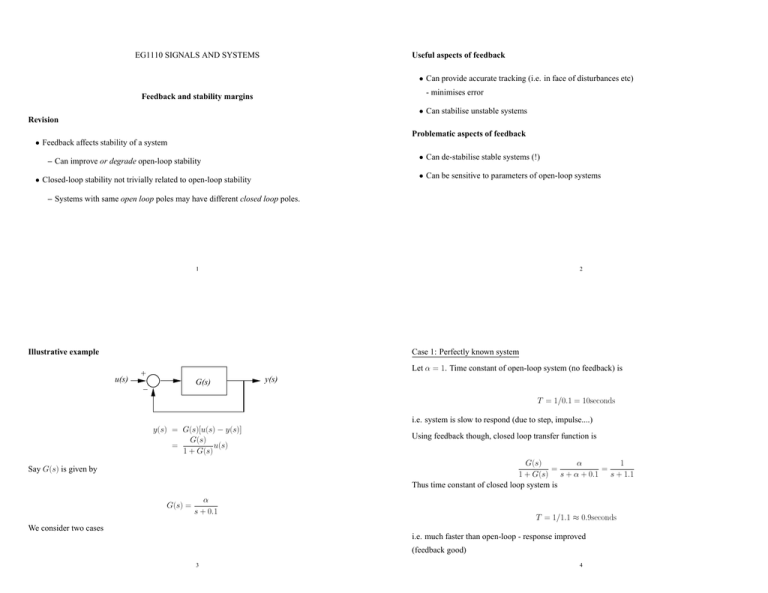
EG1110 SIGNALS AND SYSTEMS Useful aspects of feedback • Can provide accurate tracking (i.e. in face of disturbances etc) - minimises error Feedback and stability margins • Can stabilise unstable systems Revision Problematic aspects of feedback • Feedback affects stability of a system • Can de-stabilise stable systems (!) – Can improve or degrade open-loop stability • Can be sensitive to parameters of open-loop systems • Closed-loop stability not trivially related to open-loop stability – Systems with same open loop poles may have different closed loop poles. 1 2 Illustrative example Case 1: Perfectly known system u(s) Let α = 1. Time constant of open-loop system (no feedback) is + _ G(s) y(s) T = 1/0.1 = 10seconds i.e. system is slow to respond (due to step, impulse....) y(s) = G(s)[u(s) − y(s)] G(s) = u(s) 1 + G(s) Using feedback though, closed loop transfer function is α 1 G(s) = = 1 + G(s) s + α + 0.1 s + 1.1 Thus time constant of closed loop system is Say G(s) is given by G(s) = α s + 0.1 T = 1/1.1 ≈ 0.9seconds We consider two cases i.e. much faster than open-loop - response improved (feedback good) 3 4 Case 2: Imperfectly known system Notes Let α = 1 ± δ, where δ is an uncertain parameter rangining between 0 and 1.2. • In open-loop any value of δ would always result in a stable system Then in closed loop G(s) α 1±δ = = 1 + G(s) s + α + 0.1 s + 1.1 ± δ Imagine δ = 1.2, then a possible closed-loop transfer function would be G(s) = – δ would have no affect on open-loop poles. – ⇒ uncertainty has no affect on stability • In closed-loop system, uncertainty affects stability −0.2 s − 0.1 i.e we have made the closed-loop system unstable by feedback (feedback bad) 5 Stability Margins 6 Consider closed-loop transfer function • Suppose we have a closed-loop system which is stable G(s) 1 + G(s) – How do we ensure that it is insensitive to ‘modelling errors’? – Are there ways to measure how sensitive the closed-loop is to modelling errors? • Motivates the use of robust margins. • Boundary of stability is when G(s) = −1. At this point system becomes unstable. • In frequency domain G(jω) = −1 ⇒ |G(jω)|ejφ = −1 where φ = arg[G(jω)] = tan−1 7 8 =(G(jω)) <(G(jω)) For |G(jω)|ejφ = −1, this requires Gain margin – |G(jω)| = 1 – φ(jω) = −180 The amount of extra open-loop gain needed to make the closed-loop system unstable when phase is -180 degrees o • Thus we can define a stability margin in terms of “how far” the system’s frequency response is • Let ω180 be the frequency at which φ is -180 degrees i.e. φ(ω180 ) = −180 from the point -1. • Closed-loop stability margins determined by open-loop frequency response. • Then, typically, |G(jω180 )| = α < 1 • This implies we would need an extra open-loop gain of 1/α to make the closed loop system unstable. • Thus the gain margin is GM = 1 1 = α |G(jω180 )| (or −20 log10 |G(jω180 )| in dB) 9 Phase margin 10 Notes The amount of extra open-loop phase needed to make the closed-loop system unstable when the gain unity • Let ωc be the frequency at which |G(jω)| = 1 • The foregoing descriptions of gain and phase margins are simplified. • When systems have multiple cross over points, their definition becomes a little more complex • Unstable open-loop systems also have gain reduction margins i.e. |G(jωc)| = 1 • Gain/phase margins will be described in more detail in Second Year Control • Then at this frequency (typically), the phase would be such that φ(ωc) < −180o • Thus it follows that −180 = φ(ωc) − P M ⇒ −P M = −180 − φ(ωc) ⇒ P M = 180 + φ(ωc) 11 12
