Type P340
Instruction Manual
MCK-2048
March 2010
Type P340 Latch and Remote Release Mechanism
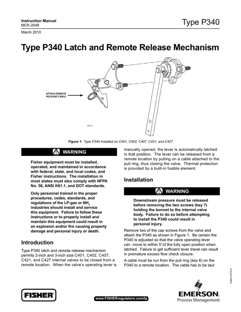
ATTACH REMOTE RELEASE CABLE T21111
Figure 1. Type P340 Installed on C401, C402, C407, C421, and C427
!
Warning
Fisher equipment must be installed, operated, and maintained in accordance
with federal, state, and local codes, and Fisher instructions. The installation in most states must also comply with NFPA No. 58, ANSI K61.1, and DOT standards. Only personnel trained in the proper procedures, codes, standards, and
regulations of the LP-gas or NH3
industries should install and service
this equipment. Failure to follow these
instructions or to properly install and
maintain this equipment could result in
an explosion and/or fire causing property
damage and personal injury or death. Introduction Installation !
Warning
Downstream pressure must be released
before removing the two screws (key 7) holding the bonnet to the internal valve body. Failure to do so before attempting
to install the P340 could result in
personal injury. Remove two of the cap screws from the valve and attach the P340 as shown in Figure 1. Be certain the P340 is adjusted so that the valve operating lever
can move to within 5°of the fully open position when latched. Failure to get sufficient lever travel can result in premature excess flow check closure. A cable must be run from the pull ring (key 6) on the
P340 to a remote location. The cable has to be taut
D450123T012
Type P340 latch and remote release mechanism
permits 2-inch and 3-inch size C401, C402, C407,
C421, and C427 internal valves to be closed from a
remote location. When the valve’s operating lever is
manually opened, the lever is automatically latched
in that position. The lever can be released from a
remote location by pulling on a cable attached to the
pull ring, thus closing the valve. Thermal protection
is provided by a built-in fusible element.
R
www.fisherregulators.com/lp
Type P340
enough for proper operation, and the hook-up may
require sufficient pulleys to keep the cable away from
the side of the tank. Pulling the cable allows the
valve’s operating lever to return to the closed position.
When closing the valve manually, pull back on the
cable attached to the release mechanism to permit the lever to close. !
Warning
Since there is strong spring force on the
operating lever, avoid getting in the way
of the lever as it moves to the closed position. Failure to do so could result in
personal injury. T14299
Maintenance A simple preventive maintenance program for the valve
and its controls will eliminate a lot of potential problems.
Fisher recommends these steps be conducted once
a month: 1. Regularly inspect the operating lever to see that it
operates freely and that there is no leakage around
the stub shaft. If there is leakage or sticking, the
packing should be replaced. 2. Check for tight closure of the seat discs regularly.
Any leakage indicates a defect in the seat caused
from wear or from dirt or scale lodging and
embedding in the seat. To check for leakage,
close the internal valve, and exhaust downstream
pressure. Close the first valve downstream from the
internal valve, and note any pressure build-up by
means of a pressure gauge. If leakage is indicated,
the seat discs should be replaced. LP-Gas Equipment
Emerson Process Management
Regulator Technologies, Inc.
Figure 2. Type P340
3. All operating controls should be regularly inspected,
cleaned, and lubricated. 4. Check to see that the Type P340 fully opens the
internal valve and operates freely to close the valve.
Parts Ordering When corresponding about this equipment, always
reference the equipment type number found on the
nameplate. A Replacement Parts List is available for the valve. When ordering replacement parts, reference the complete 11-character part number of each part.
Parts List
Key Description
1
2
3
4
5
6
7
Bracket Fusible Link Spring Pin Cotter Pin Pull Ring Screw (2 required) USA - Headquarters
McKinney, Texas 75069-1872 USA
Telephone: 1 (800) 558-5853
Telephone: 1 (972) 548-3574
For further information visit www.fisherregulators.com/lp
The Emerson logo is a trademark and service mark of Emerson Electric Co. All other marks are the property of their prospective owners. Fisher is a mark owned by Fisher Controls, Inc., a
business of Emerson Process Management.
The contents of this publication are presented for informational purposes only, and while every effort has been made to ensure their accuracy, they are not to be construed as warranties or
guarantees, express or implied, regarding the products or services described herein or their use or applicability. We reserve the right to modify or improve the designs or specifications of such
products at any time without notice.
Emerson Process Management does not assume responsibility for the selection, use or maintenance of any product. Responsibility for proper selection, use and maintenance of any Emerson
Process Management product remains solely with the purchaser.
©Emerson Process Management Regulator Technologies, Inc., 2001, 2010; All Rights Reserved
