CONTINENTAL® IGNITION SYSTEMS
Printing Instructions
CLOSE
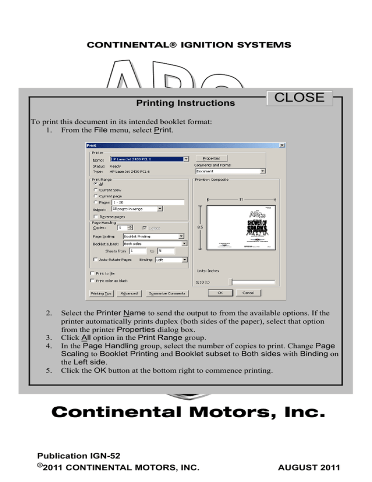
To print this document in its intended booklet format:
1. From the File menu, select Print.
2.
3.
4.
5.
Select the Printer Name to send the output to from the available options. If the
printer automatically prints duplex (both sides of the paper), select that option
from the printer Properties dialog box.
SYSTEM
in the Print Range group.
Click All option IGNITION
In the Page Handling group, select the number of copies to print. Change Page
Scaling to Booklet Printing and Booklet subset to Both sides with Binding on
the Left side.
Click the OK button at the bottom right to commence printing.
Publication IGN-52
©
2011 CONTINENTAL MOTORS, INC.
AUGUST 2011
Supersedure Notice
This manual is a revision of the information contained in Publication Part No. IGN-52, dated 15
December 2009. Previous editions are obsolete upon release of this manual.
Effective Changes for this Manual
0............... 31 August 2011
List of Effective Pages
Document Title:ABCs of the Shower of Sparks
Publication Number: IGN-52
Page
Change Page
Cover ..............................0
A......................................0
1 thru 16..........................0
Change Page
Initial Publication Date: 31 August 2011
Change Page
Change
Published and printed in the U.S.A. by Continental Motors, Inc.
Available exclusively from the publisher: P.O. Box 90, Mobile, AL 36601
Copyright © 2011 Continental Motors, Inc. All rights reserved. This material may not be reprinted, republished, broadcast, or
otherwise altered without the publisher's written permission. This manual is provided without express, statutory, or implied warranties. The publisher will not be held liable for any damages caused by or alleged to be caused by use, misuse, abuse, or misinterpretation of the contents. Content is subject to change without notice. Other products and companies mentioned herein
may be trademarks of the respective owners.
A
ABCs of the Shower of Sparks
31 August 2011
CONTENTS
A.
B.
C.
D.
E.
F.
G.
H.
I.
Introduction.................................................................................2
About Impulse Couplings............................................................2
The Most Mysterious Part of an Airplane? .................................3
Engine Ignition Theory of Operation...........................................4
Circuit Theory .............................................................................5
Circuit Analysis ...........................................................................8
At the Maintenance Hangar......................................................13
Airframe Circuits Variations ......................................................14
Ignition Switch and Starting Vibrator Reference .......................16
DISCLAIMER
Information contained in this document is for
reference only, not representative of any
particular Continental Motors ignition
system. Consult the appropriate ignition
system service manual for applicationspecific
magneto
service
and
troubleshooting instructions.
ABCs of the Shower of Sparks
31 August 2011
1
A. Introduction
An early engine starting aid was the handcranked “booster magneto” many folks
working in the aviation industry may never
have heard of one. It connected to the
aircraft magneto circuit during a hand-prop
start. By turning the crank handle at the
same time as the propeller, a stream of
high voltage was emitted into the
distributor section of the magneto. While
the booster magneto was functional, it required at least two people to
start the engine. Impulse couplings and vibrator type starting
“booster” circuits replaced the function of the external booster
magneto.
The vibrator
(shower-ofsparks) starting
booster circuit,
widely used on
aircraft engines,
is supplied with
certain
Continental
Motors S-200, S-1200 and D-3200 series ignition systems.
B. About Impulse Couplings
Impulse couplings have been used for many years on internal
combustion engines. The purpose of the impulse coupling is:
1. To “SNAP” the magneto through its firing position at a faster than
normal rate of speed, to produce a strong spark even at slower
engine cranking speeds.
2. To postpone or delay the “SNAP” until the piston nears top center
in the cylinder so ignition is retarded, or delayed to prevent a
“kickback.”
When the engine starts, the impulse feature disengages, and the
impulse coupling functions as a plain drive member as long as the
engine is running. Impulse coupling flyweights may become
magnetized, which prevents the stop-pins from engaging properly.
When this occurs, the impulse coupling must be serviced
(degaussed). Cold weather may also prevent the impulse couplings
from engaging when congealed oil dampens the flyweight's “snap”
function.
2
ABCs of the Shower of Sparks
31 August 2011
Impulse couplings produce only one spark for each cylinder firing
cycle. Under certain starting conditions, a “Shower of Sparks” ignition
may be more desirable.
C. The Most Mysterious Part of an Airplane?
The high voltage spark in a magneto ignition
system is produced by applying the same
principle that makes a half pound hammer
strike a nail with a 200 lb. force. Momentum
builds through the swing of the hammer until
it contacts the nail head.
In the ignition
system, we build up current in the coil
and then stop it by opening a set of
breaker points. In an automobile,
current is provided by the battery. In a
magneto, the current is developed in the coil by a rotating magnet.
The principle is the same in either case.
A good analogy of this principle is the action of a heavy piston in a
cylinder filled with hydraulic fluid.
Start the heavy piston down the cylinder and slam the valve shut. The
piston wants to keep moving and the pressure built up would burst the
valve if the fluid did not have another path to travel into the box
containing the rubber diaphragm. The momentum of the piston is
converted into a force which bends the diaphragm upward.
ABCs of the Shower of Sparks
31 August 2011
3
In the ignition system, we use this same principle to generate a surge
or “kick” of electrical force (current) across the coil. The current in the
coil wants to keep flowing so it builds up voltage across the ends of
the coil.
If not for the condenser, the voltage could burn the breaker points
when they open. The built up voltage surge can be amplified by
adding a transformer to the circuit. On Continental Motors magnetos,
the voltage is amplified in the magneto and distributed as high
voltage.
',675,%8725
35,0$5<
7263$5.
3/8*6
6(&21'$5<
D. Engine Ignition Theory of Operation
A piston engine has to
be cranked-it can't
start itself like an
electric
m o t o r.
Because the starter
turns the crankshaft at
fewer revolutions per
minute (RPM) than
normal
engine
operation, the lower
RPM may not turn the magneto fast enough to generate a spark to
ignite the fuel in the combustion chamber. That's why impulse
couplings or vibrators are used.
Ignition timing must be advanced to get
maximum power output from a
combustion engine at high RPM. If we try
to start the engine with advanced ignition
timing, combustion occurs too early and
the engine kicks back and fails to start.
Starting ignition can be improved by
retarding (delaying) ignition timing until
the piston is close to the top of the
4
ABCs of the Shower of Sparks
31 August 2011
cylinder on the compression stroke. If ignition occurs too late, the
engine won't develop momentum after ignition.
Both starting and running spark timing has to be synchronized to the
engine crankshaft/piston position. For best results, retarded starting
spark occurs when cylinder pressure is highest, requiring higher
voltage.
I n c ol d w e at h er t he b a t t er y,
engine oil and fuel are all
adversely affected. Engine
friction increases, fuel is more
difficult to ignite, and the battery
has less power…right when it
needs the most. Under these
conditions, a single “one-shot”
type of spark delivered by an
impulse coupling magneto may
not be enough to ignite a lean
fuel mixture in a cold cylinder.
By starting at top center, and throwing a continuous stream, or
“shower” of sparks across the spark plug, we increase the likelihood
of igniting the fuel mixture in the cylinder. The induction vibrator does
exactly this. It is a special form of buzzer which provides about 200
sparking pulses per second!
E. Circuit Theory
To keep it simple, here's how the vibrator does its job: Current flows
from the battery to the vibrator coil and contacts and on to the
magneto coil, completing its return circuit through the engine and
airplane ground.
This does two things:
• sets up a current in the magneto coil.
• magnetizes the core of the vibrator coil, which pulls the vibrator contacts
apart.
ABCs of the Shower of Sparks
31 August 2011
5
When the vibrator contacts break the circuit, the current is brought to
a sudden stop, producing the required voltage surge in the magneto
coil for ignition purposes. The condenser prevents excessive arcing
of the vibrator contacts. In most systems only one magneto is
boosted for starting. The second magneto is automatically grounded
to prevent possible advance ignition and engine “kick-back.”
To get a retarded or late spark for starting, the LEFT magneto is
assembled with two contact assemblies in it. The “ADVANCE” or
“MAIN” contacts are synchronized to the crankshaft timing mark
before piston top dead center. The “RETARD” or “START” contacts
open a few degrees after the “ADVANCE” or “MAIN” contacts open,
depending on engine requirements.
NOTE: *MAIN AND RETARD BREAKERS MAY BE
REVERSED DUE TO MAGNETO ROTATION.
The ignition switch connects the retard contacts and the main
contacts together during starting. As long as either contact is closed,
the magneto coil will be short-circuited to ground and cannot produce
ignition voltage. Thus the vibrator cannot produce a spark until the
retard contacts open.
6
ABCs of the Shower of Sparks
31 August 2011
When the engine starts, the spring loaded ignition switch is released
to the “BOTH” position. This disconnects the retard contacts, vibrator
and starter from the circuit, and removes the ground from the RIGHT
magneto.
ABCs of the Shower of Sparks
31 August 2011
7
F. Circuit Analysis
1. Figure 1 represents a magneto circuit with the engine not running
and all switches in the OFF position. As the illustration points out,
each magneto “SWITCH” input is connected to ground through
the ignition switch.
/()70$*1(72
67$576:,7&+
*1'
2))
5
6:,7&+
/
/
%27+
67$57
5(7$5'
/5
%2
5,*+70$*1(72
5
%2
9,%5$725
6
6:,7&+
,1
%$7
%$77(5<
7267$57
62/(12,'
Figure 1. Magneto Circuit OFF
8
ABCs of the Shower of Sparks
31 August 2011
2. Turn the ignition switch to the “START” (Figure 2) position. Lines
in the illustrations indicate the circuit path.
a. The starter solenoid energizes, engages the starter and turns
the crankshaft.
b. Vibrator pulses flow to both contacts in the “L” magneto but are
shorted to ground.
c. The “R” magneto is grounded through the ignition switch.
/()70$*1(72
67$576:,7&+
*1'
2))
5
6:,7&+
/
/
%27+
67$57
5(7$5'
/5
%2
5,*+70$*1(72
5
%2
9,%5$725
6
6:,7&+
,1
%$7
%$77(5<
7267$57
62/(12,'
Figure 2. Vibrator Energized
ABCs of the Shower of Sparks
31 August 2011
9
3. When the crankshaft reaches the full advance (Figure 3) firing
position, the advance contacts in the “L” magneto open but the
closed retard contacts short the vibrator current to ground. The
“R” magneto is grounded through the ignition switch so no spark
reaches either spark plug.
/()70$*1(72
67$576:,7&+
*1'
2))
5
6:,7&+
/
/
%27+
67$57
5(7$5'
/5
%2
5,*+70$*1(72
5
%2
9,%5$725
6
6:,7&+
,1
%$7
%$77(5<
7267$57
62/(12,'
Figure 3. Advance Contacts Open
10
ABCs of the Shower of Sparks
31 August 2011
4. When the crankshaft reaches the piston TOP CENTER position
in Figure 4, the retard contacts open and remove the ground from
both contacts. Vibrator pulses pass thorough the primary winding
of the “L” magneto and induce high voltage in the secondary
winding. The high voltage transmits through the distributor to the
spark plug. The left magneto will continue to supply retard spark
as long as the switch remains in the “START” position.
/()70$*1(72
67$576:,7&+
*1'
2))
5
6:,7&+
/
/
%27+
67$57
5(7$5'
/5
%2
5,*+70$*1(72
5
%2
9,%5$725
6
6:,7&+
,1
%$7
%$77(5<
7267$57
62/(12,'
Figure 4. Both Contacts Open
ABCs of the Shower of Sparks
31 August 2011
11
5. Release the ignition switch to the “BOTH” position (Figure 5) and
the circuit changes to normal operation.
a. Magnetos fire at specified ignition position.
b. The vibrator and starter are disconnected.
c. Both spark plugs fire during ignition.
/()70$*1(72
67$576:,7&+
*1'
2))
5
6:,7&+
/
/
%27+
67$57
5(7$5'
/5
%2
5,*+70$*1(72
5
%2
9,%5$725
6
6:,7&+
,1
%$7
%$77(5<
7267$57
62/(12,'
Figure 5. Normal Operation
12
ABCs of the Shower of Sparks
31 August 2011
G. At the Maintenance Hangar
General Troubleshooting
If you have an engine ignition problem, remember: the vibrator can't
do its job unless:
1. It has enough input voltage.
2. The retard and advance contacts are BOTH correctly timed.
3. The magnetos are correctly timed to the engine.
4. The vibrator is correctly adjusted internally.
Refer to the airframe maintenance manual; trace the circuit feeding
the vibrator battery current. Several components such as circuit
breakers, switches, and intermediate connections, etc. could reduce
the input voltage. Unless you have good clean connections through
the circuit, current may not reach the magneto.
Listen to the vibrator buzz while cranking the engine. The tone should
change as the magneto breaker points open and close. If no buzzing
is heard, check the voltage at the “IN” terminal of the vibrator while
cranking. Minimum voltage must be at least 8V on 12V systems or
13V on 24 V systems. If the tone doesn't change, check the magneto
wiring and the contact springs in the magneto breaker cover.
More on Troubleshooting
If the RETARD contacts don't open, you'll get no spark…and no start!
If the RETARD contacts don't close, you'll be cranking with a fully
advanced, boosted spark and may experience kick-back; this may
also result if the RETARD contacts wiring is broken, or RETARD
circuit connections are loose or damaged. If the RETARD contacts
open too late, the engine may fire but not develop the momentum to
run. Check ignition timing!
If the ADVANCE contact wiring is broken or circuit connections are
faulty the magneto will be permanently “HOT”; vibrator current will
have no path to the magneto. The tip-off to this condition is the sound
from the vibrator: instead of changing tone the vibrator will stop and
start as the engine is cranked. It is a good idea to inspect both
ADVANCE and RETARD magneto connections when difficulty is
experienced. If you can't feel the terminal, compress the contact
spring in the S-200 or D-3000 magneto slightly; you may not be
getting good contact. Look at the contact springs in the magneto with
a flashlight; dirty or burned contacts may be the cause.
ABCs of the Shower of Sparks
31 August 2011
13
H. Airframe Circuits Variations
The circuit depicted below is common, but variations exist. On some
dual engine airframes, the “IN” terminal of the vibrator connects
directly to the battery bus (usually through a circuit breaker) to allow
the same vibrator to serve both engines with the advantage of
providing full battery power to the vibrator without the increased
resistance of complex wiring circuits.
5
/
/5
%2
7267$57
62/(12,'
9,%5$725
%2
,1
)520%$77(5<
Some switches feature a spring loaded start function while others are
designed with a “PUSH-TO-START” feature. Many combinations are
available, limited only by the demand for possible start and run
combinations.
Some switches feature a spring loaded start function while others are
designed with a “PUSH-TO-START” feature. Many combinations are
available, limited only by the demand for possible start and run
combinations.
14
ABCs of the Shower of Sparks
31 August 2011
ABCs of the Shower of Sparks
31 August 2011
15
I. Ignition Switch and Starting Vibrator Reference
Ignition and Starting Switches
Part Number
Description
10-357200-1
Key, Twist/Start
10-357210-1
Key, Push/Start
10-357230-1
Lever, Twist/Start
10-357240-1
Lever, Push/Start
10-357250-1
Lever, Twist to Start/Push to Prime
10-357290-1
Key, No Start
10-400185-1
Lever, No Start
Starting Vibrators
Part Number
Description
Used with Ignition
System
10-176487-121
12VDC
S-200
10-357487-241
24VDC
S-200
10-176487-122
12VDC
S-1200
10-357487-242
24VDC
S-1200
10-382775-12
12VDC
D-2200, D-3200
10-382808-24
24VDC
D-2200, D-3200
10-400608-121
12VDC W/Relay
S-200
10-400608-241
24VDC W/Relay
S-200
10-400608-122
12VDC W/Relay
S-1200
10-400608-242
24VDC W/Relay
S-1200
10-400608-123
12VDC W/Relay1
D-2200, D-3200
10-400608-243
24VDC W/Relay1
D-2200, D-3200
1
NOTE: Not a comprehensive parts list. Consult
airframe manufacturer’s parts catalog for ignition
switch and starting vibrator application.
1. When using other than combined Continental Motors ignition and starting switches, use
starting vibrator with relay. Consult airframe parts catalog for ignition switch and starting
vibrator application.
16
ABCs of the Shower of Sparks
31 August 2011


