Series A - Selection Table & Technical Specifications Guide
MTE SERIES A dV/dt FILTERS are designed to protect AC motors from the destructive effects of peak voltages facilitated
by long cable runs between the inverter and motor. Depending on the switching time of the power semiconductor
used in the inverter and the size of the motor, cable lengths as short as eight feet can result in peak motor voltages
that exceed the rating of the motor’s insulation system. The longer the cable, the greater the problem.
GUARANTEED RESULTS - The MTE dV/dt Filter is guaranteed to meet its maximum peak motor voltage specification
(150% of bus voltage) with up to 1,000 feet of cable between the filter and the motor. It is also rated for a maximum
dV/dt of 200V per microsecond. In specific applications, the filter has provided excellent performance with cable runs
up to 3,000 feet. The dV/dt Filter has a “3% insertion impedance” which ensures motor torque is not affected by added
voltage drops from the filter. Additional benefits include cooler running motors (typically 20-40°C cooler) and a 5dbA
reduction in audible motor noise.
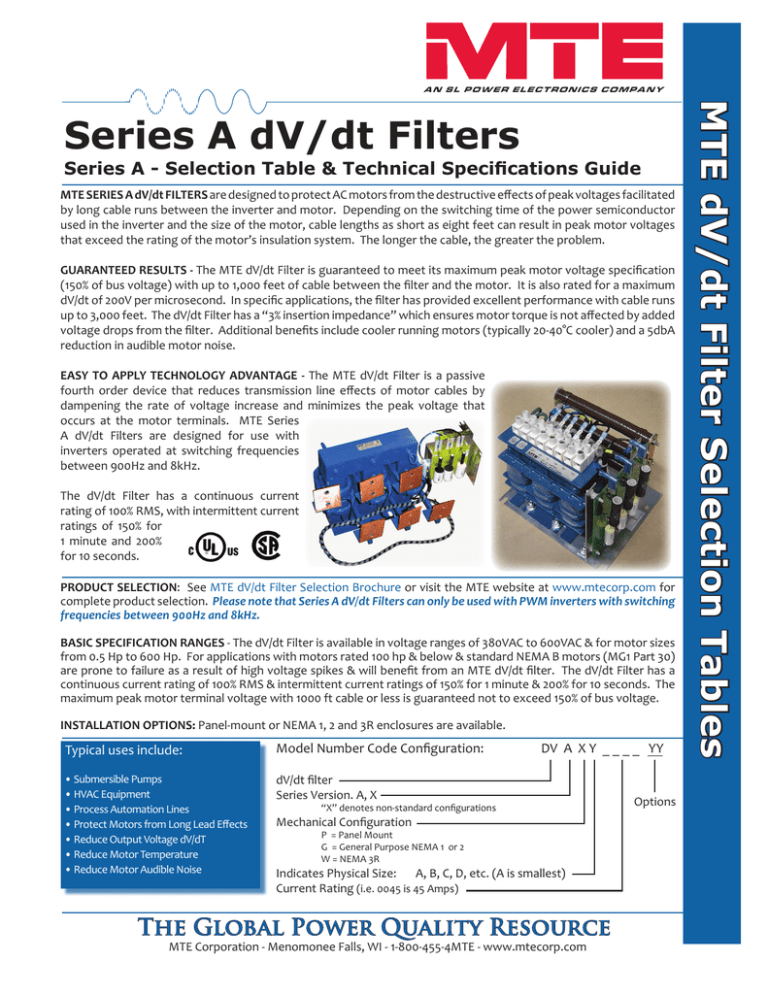
EASY TO APPLY TECHNOLOGY ADVANTAGE - The MTE dV/dt Filter is a passive
fourth order device that reduces transmission line effects of motor cables by
dampening the rate of voltage increase and minimizes the peak voltage that
occurs at the motor terminals. MTE Series
A dV/dt Filters are designed for use with
inverters operated at switching frequencies
between 900Hz and 8kHz.
The dV/dt Filter has a continuous current
rating of 100% RMS, with intermittent current
ratings of 150% for
1 minute and 200%
for 10 seconds.
PRODUCT SELECTION: See MTE dV/dt Filter Selection Brochure or visit the MTE website at www.mtecorp.com for
complete product selection. Please note that Series A dV/dt Filters can only be used with PWM inverters with switching
frequencies between 900Hz and 8kHz.
BASIC SPECIFICATION RANGES - The dV/dt Filter is available in voltage ranges of 380VAC to 600VAC & for motor sizes
from 0.5 Hp to 600 Hp. For applications with motors rated 100 hp & below & standard NEMA B motors (MG1 Part 30)
are prone to failure as a result of high voltage spikes & will benefit from an MTE dV/dt filter. The dV/dt Filter has a
continuous current rating of 100% RMS & intermittent current ratings of 150% for 1 minute & 200% for 10 seconds. The
maximum peak motor terminal voltage with 1000 ft cable or less is guaranteed not to exceed 150% of bus voltage.
INSTALLATION OPTIONS: Panel-mount or NEMA 1, 2 and 3R enclosures are available.
Typical uses include:
Model Number Code Configuration:
• Submersible Pumps
• HVAC Equipment
• Process Automation Lines
• Protect Motors from Long Lead Effects
• Reduce Output Voltage dV/dT
• Reduce Motor Temperature
• Reduce Motor Audible Noise
dV/dt filter
Series Version. A, X
DV A X Y _ _ _ _ YY
“X” denotes non-standard configurations
Mechanical Configuration
P = Panel Mount
G = General Purpose NEMA 1 or 2
W = NEMA 3R
Indicates Physical Size:
A, B, C, D, etc. (A is smallest)
Current Rating (i.e. 0045 is 45 Amps)
The Global Power Quality Resource
MTE Corporation - Menomonee Falls, WI - 1-800-455-4MTE - www.mtecorp.com
Options
MTE dV/dt Filter Selection Tables
Series A dV/dt Filters
Reflected Wave Phenomenon:
Reflected voltage wave generation occurs as a function of the output voltage rise time (dV/dt), the length
of the cables in the system, and the impedance characteristics of the motor. Motor cables become complex
transmission lines with increasing distributed parallel capacitance, series inductance and resistance, which
build up with length. At one end of the transmission line is a low impedance inverter drive. At the other end
of the transmission line is the is the soft impedance motor. The PWM variable switched energy from the
drive will reach a resonance as the leading edge works against the soft impedance motor and reflects back,
then adds to the next energy wave from the drive. This effect can cause voltage at the motor terminals to
reach 2 to 4 times the drive’s normal DC bus voltage.
The Solution:
The MTE dV/dt Filter is a passive fourth order device that reduces transmission line effects of motor cables by
dampening the rate of voltage increase and minimizes the peak voltage that occurs at the motor terminals.
When to add an MTE dV/dt Filter
Effects of Transients on the Motor
dV/dT Filter Performance
dV/dt
Filter
Current
OutputFrequency
Frequency
dV/dt
Filter
CurrentDerating
Derating for
for Drive
Drive output
22 Amp dV/dt Overall Performance 30hp 480 Vac Motor
1.05
1.05
1.80
1.60
0.90
0.9
0.85
0.85
0.80
0.8
0.75
0.75
0.70
0.7
0.65
0.65
0.6
0.60
50
50
60
60
70
70
80
80
90
90
100
100
OutputDrive
Drive Frequency,
Output
FrequencyHz
Hertz
110
110
120
120
130
130
Peak Voltage at Motor in K volts
Current Derating
Current
DeratingFactor
Factor
1.00
1
0.95
0.95
1.40
1.20
1.00
0.80
0.60
Unfiltered
1.5 x Bus
with dV/dt
Drive Bus
0.40
0.20
0.00
100 ft
500 ft
Cable Length
The Global Power Quality Resource
MTE Corporation - Menomonee Falls, WI - 1-800-455-4MTE - www.mtecorp.com
1000 ft
Selection Table Series A dV/dt Filter Technical Data - 380VAC to 600VAC
dV/dt Filter Selection:
Select filters based on the current rating of the motor for both variable torque and constant torque applications. MTE Series A
dV/dt Filters have been designed to meet motor current requirements based on NEC motor ratings. For applications that use
motors that exceed NEC current ratings, use the next larger dV/dt Filter. MTE Series A dV/dt Filters are available as open frame
panel mount or enclosures with ratings including NEMA 1, NEMA 2, and NEMA 3R.
Open Panel dV/dt Filter
Figure 1
General Purpose Enclosure
NEMA 1, 2 , & 3R
The Global Power Quality Resource
MTE Corporation - Menomonee Falls, WI - 1-800-455-4MTE - www.mtecorp.com
Product Specifications - dV/dt Filters
Refer to the Series A dV/dt Filter User Manual for Detailed Specifications
dV/dt
Filter
Current
OutputFrequency
Frequency
dV/dt
Filter
CurrentDerating
Derating for
for Drive
Drive output
1.05
1.05
Ratings:
Continuous Current Rating 100% RMS
Intermittent Current Ratings: 150% for 1 minute
200% for 10 seconds
Minimum Inverter Switching Frequency: 900Hz
Maximum Inverter Switching Frequency: 8kHz
Nominal Inverter Operating Frequency: 60Hz
Minimum: 6Hz
Maximum with de-rating: 120Hz
Altitude without de-rating: 1000 meters
Maximum ambient temperature:
50° C open filters
40° C enclosed filters
Insertion Loss: 3% of rated voltage maximum
Audible Noise:
Maximum Audible Noise Level at
Two Meters for Standard Configuration: 76dB-A
1.00
1
Current Derating
Current
DeratingFactor
Factor
150% of bus voltage
200 Volts per microsecond
0.95
0.95
0.90
0.9
0.85
0.85
0.80
0.8
0.75
0.75
0.70
0.7
0.65
0.65
0.6
0.60
50
50
60
60
70
70
80
80
90
90
100
100
110
110
120
120
OutputDrive
Drive Frequency,
Output
FrequencyHz
Hertz
dV/dT Filter Performance
22 Amp dV/dt Overall Performance 30hp 480 Vac Motor
1.80
1.60
Peak Voltage at Motor in K volts
Performance:
Maximum Peak Motor Terminal
Voltage with 1000 ft cable:
Maximum dV/dt:
1.40
1.20
1.00
0.80
0.60
Unfiltered
1.5 x Bus
with dV/dt
Drive Bus
0.40
0.20
0.00
Output Compatibility/Loading: 100 ft
Conventional 3 phase motors,
“No Load / Open Circuit” continuous operation
500 ft
1000 ft
Cable Length
Agency Approvals, UL& cUL:
Listed to UL508 type MX and CSA-C22.2 No 14-95, File E180243
3HP to 1000HP, 120VAC to 600VAC, 50/60Hz Three Phase
Note: Short Circuit rating not required under Exception No.1 of UL508A SB4.2.1
Data subject to change without notice.
1000 ft Full Load, 8kHz Switching,
Unfiltered Shielded Cable
1000 ft Full Load, 8kHz Switching
with MTE dV/dt Filter
For Technical Support: appengrg@mtecorp.com
For Sales Support: sales@mtecorp.com
World Headquarters
N83 W13330 Leon Road
Menomonee Falls
Wisconsin 53052
Toll Free 1-800-455-4MTE
Phone: (262) 253-8200
Fax: (262) 253-8222
Form 1213a-1-08
®
Visit us on the Web at:
www.mtecorp.com
© 2008 MTE Corporation
All Rights Reserved
The Global Power Quality Resource
130
130


