Product Bulletin
Lever-Lock Handlever Actuator
61.8:Lever-Lock
November 2015
D500042X012
Lever-Lock Handlever Actuators for
Fisherr 8560, A41, and A11 Valves
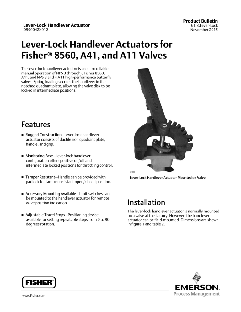
The lever‐lock handlever actuator is used for reliable
manual operation of NPS 3 through 8 Fisher 8560,
A41, and NPS 3 and 4 A11 high‐performance butterfly
valves. Spring loading secures the handlever in the
notched quadrant plate, allowing the valve disk to be
locked in intermediate positions.
Features
n
Rugged Construction—Lever‐lock handlever
actuator consists of ductile iron quadrant plate,
handle, and grip.
n
Monitoring Ease—Lever‐lock handlever
configuration offers positive on/off and
intermediate locked positions for throttling control.
W4896
n
Tamper Resistant—Handle can be provided with
padlock for tamper‐resistant open/closed position.
n
Accessory Mounting Available—Limit switches can
be mounted to the handlever actuator for remote
valve position indication.
Installation
Adjustable Travel Stops—Positioning device
available for setting repeatable stops from 0 to 90
degrees rotation.
The lever‐lock handlever actuator is normally mounted
on a valve at the factory. However, the handlever
actuator can be field‐mounted. Dimensions are shown
in figure 1 and table 2.
n
www.Fisher.com
Lever‐Lock Handlever Actuator Mounted on Valve
Product Bulletin
Lever-Lock Handlever Actuator
61.8:Lever-Lock
November 2015
D500042X012
Specifications
Lever‐Lock handlever Actuator Sizes
Handlever Length
Maximum of 432 mm (17 inches). See figure 1 and
table 2
See table 1
Construction Materials
Handle, quadrant plate, and handle grip are all ductile
iron
Valve Compatibility
JAccepts 8560 and A41 valve Double‐D shafts from
12.7 to 25.4 mm (1/2 to 1 inches)
JAccepts A11 valve square‐end shafts from 10.3 to
Dimensions and Approximate Weights
See figure 1 and table 2
15.9 mm (13/32 to 5/8 inches)
Options
JAdjustable travel stops
JLimits Switches
Maximum Torque Output
See table 1
Table 1. Handlever Actuator Sizes for Fisher 8560, A41, and A11 Valves Sizes, and Maximum Allowable Torque for
Handlever Actuators
HANDLEVER
ACTUATOR
SIZE
I
II
HANDLEVER
ACTUATOR
SIZE
I
II
8560 AND A41 VALVES(1)
CL150
3
58.2(3)
124.3
4
124.3
‐‐‐
‐‐‐
4
‐‐‐
163.9
163.9
6
163.9
163.9
‐‐‐
6
163.9
‐‐‐
‐‐‐
CL300
CL600
Maximum Allowable Torque, NSm
90.4
VALVE
SIZE,
NPS
3
515(3)
1100
4
1100
‐‐‐
‐‐‐
4
‐‐‐
1450
1450
6
1450
1450
‐‐‐
6
1450
‐‐‐
‐‐‐
Maximum Allowable Torque, LbfSin
1. 8560 and A41 torque values are based on S17400 (17‐4PH stainless steel) H1075 stem material.
2. A11 torque values are based on S17400 (17‐4PH stainless steel) H1025 stem material.
3. Do not exceed this torque regardless of actuator size.
2
A11 VALVES(2)
VALVE
SIZE,
NPS
800
Product Bulletin
Lever-Lock Handlever Actuator
61.8:Lever-Lock
November 2015
D500042X012
Table 2. Handlever Actuator Dimensions and Weights
DIMENSION
VALVE SIZE,
NPS
L
M
N
mm
HANDLEVER
ACTUATOR
WEIGHT
Kg
3
4
6
8
114
114
117
117
276
276
432
432
Inches
76
76
97
97
2.3
2.3
4.1
4.1
Lbs
3
4
6
8
4.50
4.50
4.62
4.62
10.88
10.88
17.00
17.00
3.00
3.00
3.81
3.81
5
5
9
9
Figure 1. Handlever Actuator Dimensions and Weights (also see table 2)
OPEN
SHUT
1.75 MAX
CLOSE
FLOW
M MAX
L MAX
N MAX
12B7155‐C
3
Product Bulletin
Lever-Lock Handlever Actuator
61.8:Lever-Lock
November 2015
Ordering Information
When ordering, specify:
Application
1. Valve type number, size, and shaft diameter or shaft
size with which the lever‐lock handlever actuator will
be used.
2. Valve disk rotation
D500042X012
Actuator
Refer to table 1 for maximum output torque and select
the proper size of lever‐lock handlever. For service
conditions that require higher torque capabilities than
those listed in table 1, use a manual gear actuator.
Valve
Refer to separate valve bulletins for ordering
information.
Neither Emerson, Emerson Process Management, nor any of their affiliated entities assumes responsibility for the selection, use or maintenance
of any product. Responsibility for proper selection, use, and maintenance of any product remains solely with the purchaser and end user.
Fisher is a mark owned by one of the companies in the Emerson Process Management business unit of Emerson Electric Co. Emerson Process Management,
Emerson, and the Emerson logo are trademarks and service marks of Emerson Electric Co. All other marks are the property of their respective owners.
The contents of this publication are presented for informational purposes only, and while every effort has been made to ensure their accuracy, they are not
to be construed as warranties or guarantees, express or implied, regarding the products or services described herein or their use or applicability. All sales are
governed by our terms and conditions, which are available upon request. We reserve the right to modify or improve the designs or specifications of such
products at any time without notice.
Emerson Process Management
Marshalltown, Iowa 50158 USA
Sorocaba, 18087 Brazil
Cernay, France 68700
Dubai, United Arab Emirates
Singapore 128461 Singapore
www.Fisher.com
E
4 1991, 2015 Fisher Controls International LLC. All rights reserved.


