FREE AND FORCED OSCILLATIONS – POHL´S PENDULUM.
advertisement

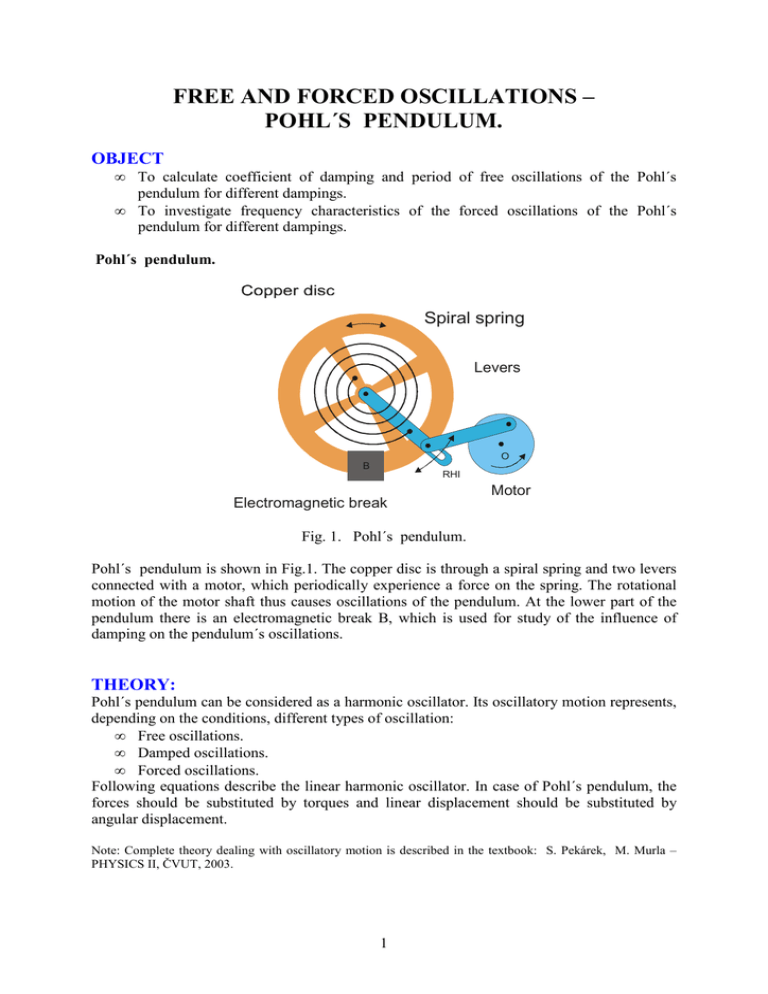
FREE AND FORCED OSCILLATIONS – POHL´S PENDULUM. OBJECT • • To calculate coefficient of damping and period of free oscillations of the Pohl´s pendulum for different dampings. To investigate frequency characteristics of the forced oscillations of the Pohl´s pendulum for different dampings. Pohl´s pendulum. Spiral spring Levers O B RHI Electromagnetic break Motor Fig. 1. Pohl´s pendulum. Pohl´s pendulum is shown in Fig.1. The copper disc is through a spiral spring and two levers connected with a motor, which periodically experience a force on the spring. The rotational motion of the motor shaft thus causes oscillations of the pendulum. At the lower part of the pendulum there is an electromagnetic break B, which is used for study of the influence of damping on the pendulum´s oscillations. THEORY: Pohl´s pendulum can be considered as a harmonic oscillator. Its oscillatory motion represents, depending on the conditions, different types of oscillation: • Free oscillations. • Damped oscillations. • Forced oscillations. Following equations describe the linear harmonic oscillator. In case of Pohl´s pendulum, the forces should be substituted by torques and linear displacement should be substituted by angular displacement. Note: Complete theory dealing with oscillatory motion is described in the textbook: S. Pekárek, M. Murla – PHYSICS II, ČVUT, 2003. 1 Free oscillations In this case there are no forces (apart of the force of gravity) acting on the pendulum. Displacement of the particle as a function of time is given by the following equation: x = A sin (ω t + ϕ ) , where A is the amplitude of oscillations, ω is angular frequency and φ is a phase angle. Angular frequency ω and period T of oscillations relates the formula 2π ω= = 2π f , where f is a frequency. T Damped oscillations In this case the pendulum motion is (apart of the force of gravity) affected by the damping force. Depending on the value of coefficient of damping there can be either underdamped motion, critical damping or overdamped motion. Displacement of the particle as a function of time is given by the following equation: x = e −δ t A sin (ω1t + ϕ ) , where δ is coefficient of damping, ω1 is angular frequency of damped oscillations and φ is a phase angle. 2π ω1 = ; ω1 = ω 2 − δ 2 . T1 Note that for the damped motion the period T1 is larger than the period T of free oscillations. The ratio of two succeeding amplitudes (separated in time by the period T1) is Ae −δ t = eδ T1 = b −δ ( t +T1 ) Ae Natural logarithm of b is called logarithmic decrement of damping Λ: Λ = ln b = δ T1 Forced oscillations In case when the pendulum is subjected to an oscillatory external force Fext = Q sin Ωt , where Q is amplitude of the oscillatory external driving force and Ω is angular frequency of the this force, the pendulum experiences forced oscillations. EXPERIMENTAL APPARATUS For study of free oscillations connect the terminals of the electromagnetic break (in the lower part of the pendulum) across the AC/DC converter to the AC terminals of the laboratory power supply. The ammeter between laboratory power supply and AC/DC converter reads the current IB. For the study of forced oscillations connect the output of the DC laboratory power supply to the terminals of the motor (labeled as 24 V, 650 mA). Respect the polarity – corresponding terminals must have the same colors. The voltmeter, labeled, as Ux should be connected to the terminals of the motor. The voltage Ux is proportional to the number of revolutions of the motor, therefore this voltage is proportional to the driving frequency of the pendulum. The upper potentiometer is used to switch on the motor and for rough regulation of the number of revolutions. The lower potentiometer is used for fine adjustment of the number of revolutions. 2 PROCEDURE Free oscillations 1. Disconnect the motor. By the small rotation of the motor shaft adjust position of the indicator on the copper disc to zero. Disconnect electromagnetic break. 2. Displace the copper disc to the one of the extreme left or right positions, release it, and with the stopwatch measure the time of 10 periods of the disc oscillations. Repeat this measurement 5 times. Calculate average value of the period T of oscillations. 3. Displace the copper disc to the left or right extreme positions, release it and start to measure the times at which the disc passes several succeeding extreme positions (on one side only). Note that oscillations are fast therefore collaboration of the members of the team is required. 4. Using the formula ϕ (t ) Λ = δT = ln , ϕ (t + T ) calculate average value of the logarithmic decrement of damping Λ: and coefficient of dumping ò. 5. Repeat the measurements described in point 2 but in this case with an electromagnetic break switched on. Adjust the current through the electromagnetic break IB to the following values: IB ≈ 0, 25A(U~ = 4V); IB ≈ 0, 40A(U~ = 6V); IB ≈ 0, 55A(U~ = 8V) and IB ≈ 0, 9A(U~ = 12V). 6. Make a table into which you will involve for particular values of current IB following quantities: T, f, Λ and δ. Make a graph of the dependence of the maximum displacement of the pendulum on time. Forced oscillations 1. Disconnect electromagnetic break. As far as you are going to investigate the dependence of amplitude of oscillations on the frequency of the driving force (that is on number of revolutions of the motor) you have first of all to find the dependence of the number of revolutions of the motor on the voltage Ux. Because this dependence is linear you have to determine relation between the voltage and number of revolutions. For higher accuracy use the time of at least ten revolutions. 2. Examine the dependence of the amplitude of oscillations on the frequency of the driving force for the case, when the electromagnetic break is disconnected. As far as the zero value of the pointer on the disc frequently does not match with the zero value on the scale, find zero value of the pointer readings by calculating average value of the extreme displacements of the pointer. In the vicinity of the resonance use a smaller step. (Neglect the frequencies for which the pointer will collide with the limiting points on the pendulum). Do not forget that it is necessary to wait until the transition process is over. 3. Repeat the measurements described in point 2 with an electromagnetic break switched on. Adjust the current through the electromagnetic break IB to the following values: IB ≈ 0, 25A(U~ = 4V); IB ≈ 0, 40A(U~ = 6V); IB ≈ 0, 55A(U~ = 8V) and IB ≈ 0, 9A(U~ = 12V). 4. Make a graph of the dependence of amplitude on the driving frequency. 3


