EM 3 Section 10: Electromotive force and Faraday`s Law 10. 1. emf
advertisement

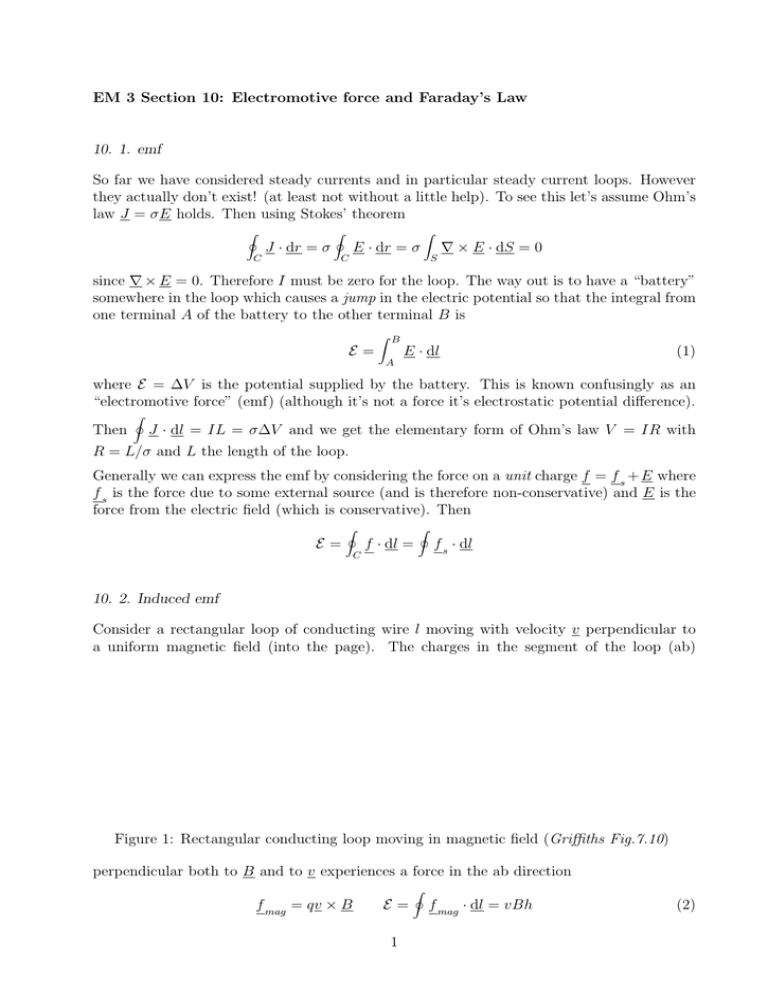
EM 3 Section 10: Electromotive force and Faraday’s Law 10. 1. emf So far we have considered steady currents and in particular steady current loops. However they actually don’t exist! (at least not without a little help). To see this let’s assume Ohm’s law J = σE holds. Then using Stokes’ theorem I J · dr = σ C I E · dr = σ Z C ∇ × E · dS = 0 S since ∇ × E = 0. Therefore I must be zero for the loop. The way out is to have a “battery” somewhere in the loop which causes a jump in the electric potential so that the integral from one terminal A of the battery to the other terminal B is E= Z B E · dl (1) A where E = ∆V is the potential supplied by the battery. This is known confusingly as an “electromotive force” (emf) (although it’s not a force it’s electrostatic potential difference). Then I J · dl = IL = σ∆V and we get the elementary form of Ohm’s law V = IR with R = L/σ and L the length of the loop. Generally we can express the emf by considering the force on a unit charge f = f s + E where f s is the force due to some external source (and is therefore non-conservative) and E is the force from the electric field (which is conservative). Then E= I f · dl = I C f s · dl 10. 2. Induced emf Consider a rectangular loop of conducting wire l moving with velocity v perpendicular to a uniform magnetic field (into the page). The charges in the segment of the loop (ab) Figure 1: Rectangular conducting loop moving in magnetic field (Griffiths Fig.7.10) perpendicular both to B and to v experiences a force in the ab direction f mag = qv × B E= 1 I f mag · dl = vBh (2) where h is the length from a to b. Aside: you may worry that a magnetic force f mag = qv × B should do no work! —this is because if the charge q moves dl = vdt then dWmag = f mag · dl = q(v × B) · vdt = 0. So actually it is the person pulling the loop that is doing the work to produce a current i.e. when the current flows in ab it creates a magnetic force df mag = dI × B to the left on an element of the wire and this must be balanced by a pulling force to the right. Now consider the magnetic flux through the loop ΦB = Z B · dS = BA = Bhx where A is the area and the flux integral is simply current× area here becuase dS k B in this example. dΦB dx = Bh = −Bhv dt dt Therefore comparing with (2) we see E =− dΦB dt (3) This result actually holds for general loops, B and v (for proof see Griffiths fig. 7.13). It is known as the flux rule or Faraday’s law of induction. E is known as an induced electromotive force (emf ). 10. 3. Faraday’s Law As we have seen in (3) the induced emf can be understood in terms of the timeR variation of the magnetic flux through the current loop. Note that the magnetic flux φB = S B · dS can R be changed by varying the field B, the surface dS or the angle between B and dS. Figure 2: Summary of Faraday’s experiments (Griffiths Fig. 7.20) In a famous series of experiments Faraday found that an emf can be induced by: 1. Pulling a current loop through a magnetic field. 2. Moving the magnet and area containing a field to the left 3. Changing the strength of the field 2 N.B. In case 2. we clearly see from relativity that the two scenarios must yield the same result i.e. in both cases the loop moves relative to the magnet with the same velocity. But actually this has enormous consequences for the physics: in case 2 the loop is stationary therefore, for the charges to feel a force, there must be an electric field present i.e. we deduce that the changing magnetic field induces an electric field. See Griffiths chapter 7.2 for discussion 10. 4. Differential form of Faraday’s Law Let us take Faraday’s law (3) and use our definition of emf (1) to find I Z d Z ∂B E · dl = − B · dS = − · dS dt ∂t where in the last equality we have assumed that only the magnetic field is changing Now use Stokes’ theorem I C E · dl = Z (∇ × E) · dS = − S Z S ∂B · dS ∂t which holds for an arbitrary surface A implying ∇×E =− ∂B ∂t (4) This is the full third fundamental law of electromagnetism MIII. The curl of an electric field around an axis is proportional to the time variation of the magnetic field along the axis. 10. 5. Lenz’s Law Determing the sign of the flux in Faraday’s law often proves troublesome. But there is a simple rule known as Lenz’s Law that gives the right answer: The induced emf always acts to oppose the change that causes it or “Nature abhors a change in flux!” • In the case of the moving current loop at the start of this lecture, there is a force on the current in the wire f = IlB which acts to decelerate the wire. • Additional work has to be done to move a current loop into or out of a magnetic field, or through a non-uniform field. This is to overcome the induced emf. • For a rotating current loop (see next lecture), there is a torque m × B due to the magnetic moment of the loop. This always acts to slow down the rotation. • A time-varying magnetic field produces eddy currents in conducting loops. The dipole fields of these loops act to reduce the time-variation. 3 10. 6. Faraday’s Law in terms of Magnetic Vector Potential The two equations: ∇×E =− ∂B ∂t B =∇×A can be combined to give: ∇×E =− ∂ (∇ × A) ∂t A solution to this equation is clearly: E=− ∂A ∂t (5) The electric field due to induction can be expressed as the time-derivative of the magnetic vector potential. The general solution is obtained by adding in a static electric field, which is expressed as the gradient of the scalar potential: E=− ∂A − ∇V ∂t (6) This does not change the form of Faraday’s law because “curlgrad = 0 ”. Note that the equation E = −∇V only applies to electrostatic situations when there are no time-varying fields. Thus we can think of two kinds of electric field: those coming from a static charge distribution and which may be written as E = −∇V ; those coming from a changing magnetic field and ∂A which may be written E = − . ∂t 4


