IMD Characteristics and Performance Issues in Wide Bandwidth
advertisement

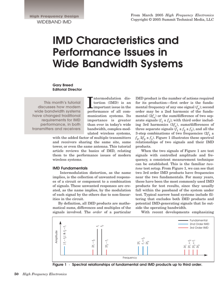
From March 2005 High Frequency Electronics Copyright © 2005 Summit Technical Media, LLC High Frequency Design WIDEBAND IMD IMD Characteristics and Performance Issues in Wide Bandwidth Systems Gary Breed Editorial Director I ntermodulation distortion (IMD) is an important issue in the performance of all communication systems. Its importance is greater than ever in today’s wide bandwidth, complex-modulated wireless systems, with the added factor of multiple transmitters and receivers sharing the same site, same tower, or even the same antenna. This tutorial article reviews the basics of IMD, relating them to the performance issues of modern wireless systems. IMD Fundamentals 3f2 2f2 + f1 2f1 + f2 3f1 2f1 2f2 f2 Fundamental 2nd Order IMD 3rd Order IMD 2f2 – f1 f1 2f1 – f2 |f1 – f2| & f2 – f1 Amplitude Intermodulation distortion, as the name implies, is the collection of unwanted responses of a circuit or component to a combination of signals. These unwanted responses are created, as the name implies, by the modulation of each signal by the others due to non-linearities in the circuit. By definition, all IMD products are mathematical sums, differences and multiples of the signals involved. The order of a particular IMD product is the number of actions required for its production—first order is the fundamental frequency of any one signal (fn); second order may be a 2nd harmonic of the fundamental (2fn) or the sum/difference of two separate signals (f1 ± f2); with third order including 3rd harmonics (3fn), sums/differences of three separate signals (f1 ± f2 ± f3), and all the 3-step combinations of two frequencies (2f1 ± f2, 2f2 ± f1). Figure 1 illustrates these spectral relationships of two signals and their IMD products. When the two signals of Figure 1 are test signals with controlled amplitude and frequency, a consistent measurement technique can be established. This is the familiar twotone test setup. From Figure 1, we can see that two 3rd order IMD products have frequencies near the two fundamentals. For many years, these have been the most commonly used IMD products for test results, since they usually fall within the passband of the system under test. Typical narrow band systems include filtering that excludes both IMD products and potential IMD-generating signals that lie outside the operating bandwidth. With recent developments emphasizing f1 + f2 This month’s tutorial discusses how modern wide bandwidth systems have changed traditional requirements for IMD performance, in both transmitters and receivers Frequency Figure 1 · Spectral relationships of fundamental and IMD products up to third order. 50 High Frequency Electronics High Frequency Design WIDEBAND IMD Fundamental IMD Products (a) (b) (c) Figure 2 · A comparison of two-tone IMD (a), multi-carrier IMD (b) and wide bandwidth IMD (c). Note the progression from a few discrete frequency products to a noise-like spread of products over the entire spectrum adjacent to the passband. broadband systems and simplified circuitry, the filtering will have much less influence on the IMD performance of today’s wireless equipment. This means that IMD specifications and measurements must be different as well. IMD in Transmitters and Receivers IMD in receivers has been the primary focus in narrow bandwidth systems. In receivers, the signals that are the source of IMD are external, other users of the radio spectrum, operating on nearby frequencies. As such, the characteristics of the IMD products—modulation, noise, specific frequencies, etc.—are beyond the designer’s control. Specifications are typically established for a design that can operate in the presence of signals with a predictable range of signal strengths. This robust receiver performance is easier to achieve in narrow bandwidth applications because, as noted above, many interferers and IMD products can be eliminated by filtering. In today’s wide bandwidth systems, the wide passbands of filters requires receivers to have higher performance in other parts of the circuit. In transmitters, the problem is different. Most IMD is caused by nonlinearities in the amplifier chain, and 52 High Frequency Electronics the “signals” are the carrier and modulation sidebands. In a narrowband system, there are fewer of these sources. The IMD products from signals close to the center frequency are also near the center frequency, and the higher-order products that are further out have much lower amplitude than the close-in 3rd or 5th order products. Thus, there has been minimal concern for IMD performance of narrow band transmitters. Multi-Channel Systems The first new requirement of current wireless systems is the need to operate in the presence of numerous other signals. These signals may be nearby, even amplified together in the same transmitting equipment, or they may be farther away, from other cell sites or from handsets anywhere in range of the site. It is easy to visualize the challenge of receiving a weak signal from a low-power handset while nearby transmitters are generating tens of watts on other channels. Wide Bandwidth Systems Complex modulation and their resulting wide bandwidth signals generate IMD products that also have wide bandwidths. These IMD products are much more troublesome than discrete frequency or narrow bandwidth products, since their potential for interference covers a much wider part of the spectrum. Figure 2 is a simplified illustration of the progression from two-tone IMD behavior to multi-carrier IMD, and finally to wide bandwidth signals and the resulting IMD sidebands. Note that the total bandwidths represented in (b) and (c) may be tens of MHz, compared to bandwidths as little as a few kHz in (a). In receivers, these wide bandwidth distortion products have the effect of raising the noise floor, thereby reducing sensitivity and limiting communication range. IMD in wide bandwidth systems is an even greater problem for transmitters—wideband signals generate wideband IMD products. Distortion products are not confined to frequencies adjacent to the center frequency as they are in narrowband systems. Instead, they extend well beyond the passband of the modulated signal. This behavior has created new specifications for IMD performance, adding terms like adjacent channel power ratio (ACPR) to the engineering vocabulary. Reducing ACPR in transmitters requires a different set of design solutions than reducing IMD in receivers. Low distortion means high linearity, but the most common linear power amplifiers (class A) are inefficient. Class A amplifiers consume a lot of DC power, shortening battery life in portable equipment and generating excessive heat in base stations. This problem has given rise to several innovative techniques for improving linearity with better efficiency. Techniques like dynamic bias, feedback and feedforward correction, and digital predistortion have helped improve the linearity/efficiency performance of power amplifiers. Signal-to-Noise Requirements IMD behavior has implications on other aspects of system performance. From Figure 2(c), we can see that wide bandwidth signals create IMD products that resemble noise. Transmitted high-order IMD products will extend to frequencies far away from the center of the signal passband, raising the noise floor for all nearby receivers. Most wireless systems include consideration for this energy in their operational standards, but flawed, damaged or improperly installed equipment can result in higher IMD levels than expected. This is especially troublesome when the expected signal levels are low to being with, and IMD products far from the transmitter’s operating frequency can cause interference. Passive IMD The broadband “noise” of wide bandwidth IMD has created another new issue for today’s wireless systems—passive intermodulation distortion. A wireless base station site may have dozens of frequencies in operation at once, with some systems sharing feedlines between transmitter and receiver. Although designed to meet the performance requirements of the system, it has been found that passive components (coaxial cable, connectors, filters, couplers, etc.) can generate IMD products at a significant level. To avoid unwanted IMD from these components, materials are carefully chosen, and finished products are tested for IMD contribution at the expected power levels and frequencies of operation. Summary This short tutorial was intended to raise awareness of the issues of IMD in modern wireless systems. IMD has long been a significant issue in receiver and transmitter design, but with today’s wide bandwidths, the similarly wideband characteristics of IMD products must now be dealt with. In addition, with base stations having many channels in operation, usually with other transmitters sharing the site, there are more potential sources (and victims) of performance-degrading IMD products. Waveguide to Coax Adapters • 18.0 to 70.0 GHz • Ridged Design • Low VSWR • Low Cost .95 9 9 $ as 100) As Low ea. (Qty. • Made in USA


