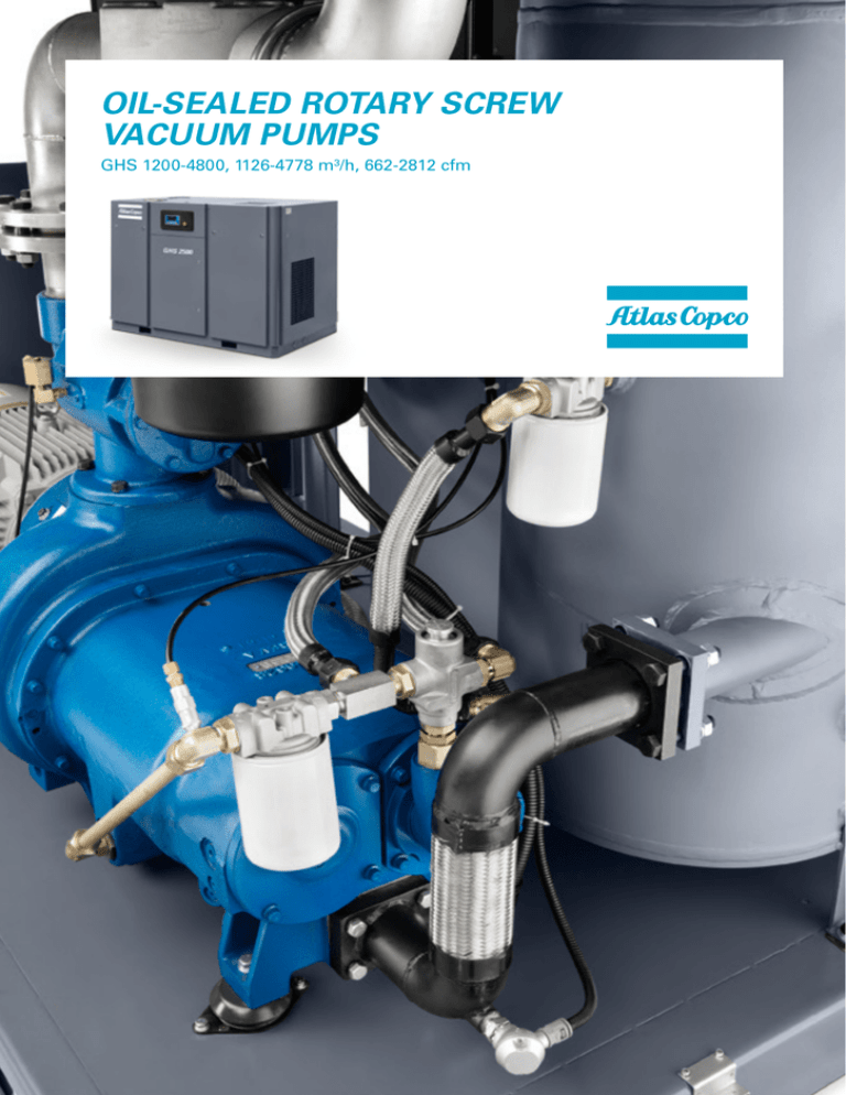
OIL-SEALED ROTARY SCREW
VACUUM PUMPS
GHS 1200-4800, 1126-4778 m³/h, 662-2812 cfm
RELIABLE
GENERAL VACUUM
FOR CRITICAL
APPLICATIONS
Atlas Copco, the industry leader in compressed
air solutions, has transferred its highly efficient
and ultra-reliable screw compression technology
to vacuum applications. The result is the
GHS 1200-4800 series of oil-sealed rotary screw
vacuum pumps. Providing around 4,000 m3/h
of vacuum pumping performance across six models,
the GHS series is ideal for critical applications
in printing, electronics, plastics, packaging,
woodworking, bottling, canning and similar
exacting industries.
Robust technology
The GHS 1200-4800 combine a technologically advanced
screw design with robust and highly regarded oil-sealed
rotary technology to produce a state-of-the-art,
market-leading product.
High reliability
In the GHS 1200-4800 range of vacuum pumps, industry-leading
screw technology meets many years of vacuum know-how.
Add a conservative approach to machine speed and you have all
the benefits of Atlas Copco’s screw element, including inherent
reliability, optimal efficiency and life cycle costs.
Outstanding efficiency & ease of use
GHS rotary screw vacuum pumps outperform many other
vacuum technologies in their operating pressure range.
They are available ready to use, with all the options
you need, and supported by the best know-how.
STATE-OF-THE-ART, RELIABLE VACUUM
TECHNOLOGY
1
Slow rotor speed
•Ensuring that GHS 1200-4800 vacuum pumps are quiet
– from 82 dB(A) – so they can be located alongside your
machine in areas where people work.
•Guaranteeing high reliability and extreme durability.
2
Lift-out panels
Eliminating the need for swing-out doors,
saving valuable space.
3
Innovative porting
•Optimizing performance when cycling from atmospheric
pressure to the operating vacuum level.
•Preventing internal and efficiency sapping back-pressures during operation
close to atmospheric pressure. The result is fast response to process changes.
4
Sound-insulated canopy
•Reduced sound levels.
•Enhancing the appearance of the vacuum pump.
8
Highly efficient oil mist separators
•Easily replaceable cartridge type elements sized to minimize
back-pressure and optimizing the delivered performance.
•Ensuring long operating life with a minimum number
of service interventions.
•Allowing operation close to atmospheric pressure,
without the consequences often found when
excessive optimization takes place.
7
Generously matched motors
GHS 1200-4800 vacuum pumps are durable, highly reliable and
fitted with generously rated motors making them last a lifetime.
6
Adjustable oil thermostat
•Preventing condensed water vapor from contaminating
the oil reservoir, even in demanding conditions.
•Consistent and continuous performance during humid
duties with minimal impact on component lifetime within
the oil circuit.
5
Modulating valve fitted directly
to pump inlet
•Allowing delivered performance to be matched
to actual demand.
•Minimizing fluctuations in system vacuum level.
•Reducing wear and maintenance, as a result of
fewer stops/starts.
OPTIMUM VACUUM
CONTROL FOR FIXED
SPEED OPERATION
All GHS 1200-4800 fixed speed vacuum pumps are
fitted with a modulating vacuum control valve at
the pump inlet as standard. An additional vacuum
control device is therefore unnecessary, unless the
vacuum levels at particular points of use need to be
varied. Many other common vacuum technologies
utilize ‘air bleed’ to control vacuum level with the
additional function of maintaining mechanical
integrity in low flow conditions.This is not necessary
with Atlas Copco’s fixed speed screw technology,
leading to optimum energy savings.
Control valve
Power
< 10 mbar
Pump-side
System
Vacuum
Vacuum
Atmospheric pressure
Controller
kW savings
Vacuum
kW @ vacuum
Significant energy savings
Modulating valve fitted directly
to pump inlet
The valve’s position is controlled by Atlas Copco’s unique
PLC controller to provide accurate set point control within
an adjustable pressure band, which can be narrow or wide.
The main benefits include:
• Precise matching of delivered capacity to the actual demand.
• Minimized fluctuations in system vacuum level.
• Reduced wear and maintenance, as a result of
fewer stops/starts.
When the GHS 1200-4800 vacuum pump is delivering
performance greater than that required by the process,
significant energy savings can be achieved. With other
technologies, this excess capacity is normally wasted by
‘bleeding off’ or running at a slightly higher vacuum level
than is needed. The GHS 1200-4800 save energy in falling
demand conditions by progressively lowering the
pressure level at the pump inlet to below that
experienced at the process. This happens automatically
without the need to adjust machine settings. It also
suppresses unnecessary stops/starts whilst catering for
continuous fluctuations in demand, thereby minimizing
wear. The result is longer life and less maintenance.
FLOW CHARTS
GHS air-cooled
GHS water-cooled
1
1
2
2
3
3
9
9
6
6
7
4
4
7
5
5
6
8
8
Air Flow
1. Inlet
2. Inlet filter
Intake air
3. Modulating control valve
4. Vacuum stage = screw element
Air/oil mixture
5. Oil mist separator
6. Oil filters
Oil
Water
7. Oil cooler
8. Oil pump
9. Vent
Vent
Working principle
As the rotors turn, air is drawn into the rotor housing through the inlet port. Air is then trapped as the inlet port is closed off. As
rotation continues, the air is conveyed to the discharge side and forced out of the discharge port. Oil is present within the twin screw
stage to lubricate, seal and cool the wetted parts. This oil is separated from the air within the oil mist separator before being
discharged to the atmosphere. The compression cycle of a rotary vacuum pump is a continuous process and is therefore relatively
pulsation free.
Inlet port
Cylinder
Male rotor
Intake
Compression
Discharge
Female rotor
Discharge port
The oil mist separator (eliminator) has the function of retaining oil within the vacuum pump oil reservoir and allowing the evacuated
air to be cleanly and safely discharged to the atmosphere. The process takes place in a number of stages which firstly separate out
the ‘heavier’ oil components, by cyclonic separation, then pre-filtration and finally coalescence. Here small droplets and mists are
combined into large droplets which fall by gravity back to the oil reservoir.
AVAILABLE ACCESSORIES & OPTIONS
Liquid separators
GHS 1200
GHS 1600
GHS 2500
GHS 4800
•
•
•
•
•
•
Inlet filters
Vacuum tanks
•
•
•
•
Check valves & isolation valves
•
•
•
•
Vacuum gauges
•
•
•
•
Multiple pump controllers
•
•
•
•
Water-cooled
•
•
•
•
Phase sequence protection
•
•
•
•
Vacuum oil PG plus for extended duty
•
•
•
•
Food grade oil
•
•
•
•
Air-cooled
: Standard
• : Optional
- : Not available
Performance curves
Pumping speed (Am³/h)
4500
4000
3500
3000
2500
2000
1500
1000
500
0
1
50 Hz
10
100
1000
mbar (hPa)
Pumping speed (Am³/h)
2000
1800
1600
1400
1200
1000
800
600
400
200
0
60 Hz
1
10
100
1000
mbar (hPa)
GHS 4800
GHS 2500
GHS 1600
GHS 1200
Pump performance measured at the inlet pressure and 20°C. Accuracy is +/- 10%.
TECHNICAL SPECIFICATIONS GHS 1200-4800
Maximum shaft power
MODEL
50 Hz version
Air-cooled
Water-cooled
m³/h
cfm
mbar
(hPa)
32.2
1126
662
10
7.5
41.45
55.6
1601
942
10
75.2
54.85
73.5
2432
1431
162.5
118.87
159.4
4778
2812
kW
hp
kW
hp
GHS 1200
23.9
32
24.03
GHS 1600
42.7
57.3
GHS 2500
56.1
GHS 4800
121.2
Maximum shaft power
MODEL
60 Hz version
GHS 1600
Ultimate
pressure
Pumping speed
Air-cooled
kW
hp
kW
hp
51.65
69.2
50.4
67.6
Dimensions (L x W x H)
Weight
mm
kg
lbs
DN 125
2040 x 1280 x 1480
1439
3164
7.5
DN 125
2560 x 1710 x 1970
2471
5434
10
7.5
DN 200
2560 x 1710 x 1970
2707
5953
10
7.5
DN 200
2990 x 1990 x 2000
4277
9405
Ultimate
pressure
Pumping speed
Water-cooled
torr
Inlet
connector
m³/h
cfm
mbar
(hPa)
torr
1665
980
10
7.5
Inlet
connector
DN 125
Dimensions (L x W x H)
Weight
mm
kg
lbs
2560 x 1710 x 1970
2471
5434
We stand by our responsibilities towards our customers, towards the environment and the
people around us. We make performance stand the test of time. This is what we call –
Sustainable Productivity.
www.atlascopco.com/vacuum
2935 0968 41 © 2015, Atlas Copco, Belgium. All rights reserved. Designs and specifications are subject to change without notice or obligation. Read all safety instructions in the manual before usage.
COMMITTED TO SUSTAINABLE PRODUCTIVITY


